


Make sure that the part numbers match the unit being replaced. The
chassisShow
command displays information about the router blades,
including part numbers, serial numbers, and additional status.
5.
Ensure that traffic is not flowing through the router blade (all port status
LEDs
8
and
11
should be off) prior to disconnecting cables.
Note:
Before removing any cables from the faulty router blade, label the
cables or make a note of the cable order by identifying each cable by
the physical port it attaches to. This will reduce confusion when you
reattach cables. If two router blades are being replaced, install one blade
at a time.
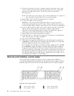
6.
Disconnect all cables and remove the SFP transceivers from the Fibre Channel
(
7
) and GbE (
10
) ports as required.
7.
Turn the router blade off by sliding the on/off switch in the top ejector down,
to the off position (
4
). This initiates a hot-swap request.
8.
Wait for the power LED (
5
) to turn off in response to the hot-swap request
before removing the router blade.
9.
Unscrew the captive screws (
3
) from the top (
2
) and bottom (
12
)
ejectors on the blade using a Phillips screwdriver.
10.
Lever both ejectors open simultaneously to approximately 45 degrees, and
pull the router blade out of the chassis.
11.
If the blade is not being replaced by another router blade, install a filler panel
to ensure correct cooling of the chassis and protection from dust. See
“Installing a filler panel” on page 76 for instructions.
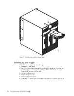
Installing a router blade
You can install up to two FR4-18i router blade in slots 1–4 or 9-12. If you are
installing two router blades, install one in one of the slots 1–4, and the other in one
of the slots 9-12 to maintain proper cooling. The control processor (CP) blades
occupy slots 6 and 7. The core switch (CR) blades occupy slots 5 and 8. Any slots
that are not occupied by a port blade, router blade, or CP blade must have a filler
panel installed to ensure proper cooling of the chassis and protection from dust. If
you are performing a new installation of a router blade, you must either remove
the filler panel or a port blade from the slot where you will install the router blade.
Attention:
All ports on the router blades are by default, persistently disabled to
avoid unintentional merging of fabrics. Before you can successfully configure FCIP
tunnels, you must enable the ports. When the blade is first powered up, all port
status LEDs will continue to flash amber. This is normal. Use the
portCfgShow
command to view the status of the ports. Use the
portCfgPersistentEnable
command to enable a port. Refer to the
Fabric OS Administrator's Guide
and the
Fabric OS Command Reference Manual
for more information on these commands.
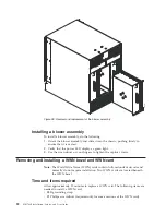
To install an FR4-18i router blade, complete these steps (refer to Figure 35 on page
85 for blade component locations):
1.
Enter the
chassisConfig
command, and verify that it is in mode 5. If the
chassisConfig mode is 5, this step is complete. If not, enter the
chassisConfig
5
command.
Attention:
Changing the
chassisConfig
mode requires a reboot, and is
disruptive to SAN768B operation.
2.
Select an empty slot from slots 1-4 or 9-12 to install the router blade.
86
SAN768B Installation, Service, and User Guide
Содержание SAN768B
Страница 2: ......
Страница 8: ...vi SAN768B Installation Service and User Guide ...
Страница 12: ...x SAN768B Installation Service and User Guide ...
Страница 14: ...xii SAN768B Installation Service and User Guide ...
Страница 16: ...xiv SAN768B Installation Service and User Guide ...
Страница 28: ...xxvi SAN768B Installation Service and User Guide ...
Страница 32: ...xxx SAN768B Installation Service and User Guide ...
Страница 42: ...10 SAN768B Installation Service and User Guide ...
Страница 62: ...30 SAN768B Installation Service and User Guide ...
Страница 78: ...46 SAN768B Installation Service and User Guide ...
Страница 100: ...68 SAN768B Installation Service and User Guide ...
Страница 154: ...122 SAN768B Installation Service and User Guide ...
Страница 178: ...146 SAN768B Installation Service and User Guide ...
Страница 184: ...152 SAN768B Installation Service and User Guide ...
Страница 202: ...170 SAN768B Installation Service and User Guide ...
Страница 207: ......
Страница 208: ... Part Number 45W8666 Printed in USA GA32 0574 05 1P P N 45W8666 ...