


Table 15. ICL connector port LEDs
LED purpose
Color
Status
Recommended
action
LINK LED
No light (LED is off)
No ICL, or ICL cable
present but no
connection.
Ensure that the ICL
cable is correctly
installed.
Steady green
ICL connected.
No action required.
ATTN LED
No light (LED is off)
ICL operational.
No action required.
Blinking amber
Attention required.
Ensure that the ICL
cable is correctly
installed.
Follow this procedure to remove and install the ICL cables. Refer to the
Fabric OS
Administrator’s Guide
for the configuration procedure and requirements.
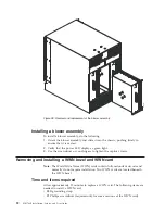
Figure 43 shows the two ends of an ICL cable. The ICL cables (2 meters long) and
the ICL connectors on the CR8 core switch blades are color-coded and labeled for
ease of installation. Figure 44 on page 101 through Figure 49 on page 106 show the
acceptable cabling configurations for the inter-chassis link (ICL) feature. Connect
the ICL cables in one of the configurations shown. The cables can connect ICL
connector ports on the SAN768B core switch blades (CR8) or SAN384B core switch
blades (CR4S-8). Figure 48 on page 105 and Figure 49 on page 106 show 3-way ICL
connections between SAN768B and SAN384B models.
Time and items required
The replacement procedure for an ICL cable takes less than five minutes. A
replacement ICL cable is the only item needed.
Removing an ICL cable
Attention:
To prevent the latch mechanism from wear, use the color-coded
(green) latch-release tab for cable removal. Pull the tab to disengage the retention
latch before cable removal.
ICL 1
ICL 0
384b025
Figure 43. ICL cable
Chapter 5. Removing and installing components
99
Содержание SAN768B
Страница 2: ......
Страница 8: ...vi SAN768B Installation Service and User Guide ...
Страница 12: ...x SAN768B Installation Service and User Guide ...
Страница 14: ...xii SAN768B Installation Service and User Guide ...
Страница 16: ...xiv SAN768B Installation Service and User Guide ...
Страница 28: ...xxvi SAN768B Installation Service and User Guide ...
Страница 32: ...xxx SAN768B Installation Service and User Guide ...
Страница 42: ...10 SAN768B Installation Service and User Guide ...
Страница 62: ...30 SAN768B Installation Service and User Guide ...
Страница 78: ...46 SAN768B Installation Service and User Guide ...
Страница 100: ...68 SAN768B Installation Service and User Guide ...
Страница 154: ...122 SAN768B Installation Service and User Guide ...
Страница 178: ...146 SAN768B Installation Service and User Guide ...
Страница 184: ...152 SAN768B Installation Service and User Guide ...
Страница 202: ...170 SAN768B Installation Service and User Guide ...
Страница 207: ......
Страница 208: ... Part Number 45W8666 Printed in USA GA32 0574 05 1P P N 45W8666 ...