


Cable organization
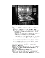
The cable management comb (
5
in Figure 1 on page 3) is attached to the chassis
under the chassis door and allows for simple cable management. The comb can be
installed without service disruption.
Route the cables down in front of the blades to keep LEDs visible. Leave at least
one meter of slack for each fiber optic cable to provide room to remove and
replace blades.
Attention:
Do not route the cables in front of the air exhaust vent, which is
located at the top of the port side of the chassis.
The FC8-64 high density port blade cannot use the standard LC cables because the
pitch between optics in the new mSFP transceiver is smaller than in standard SFPs.
Patch cables and panels can be used to attach standard size cabling to the blade if
necessary. Figure 12 illustrates the mSFP to SFP patch cable. The mSFP transceivers
are used only with the FC8-64 port blade. Narrower OM-3 LC cables are used to
connect the FC8-64. These cables are offered by several major manufacturers.
Contact your IBM representative for options regarding different cable and patch
panel configurations to simplify cable management with higher density FC8-64
port blades.
1
mini-SFP connector
3
1.6 mm cable
2
Duplex clip (black)
4
SFP connector
Note that the duplex clip on the mSFP end of the cable is black for easier
recognition. See Table 25 on page 141 for a listing of the qualified mSFP optical
cables for the FC8-64 port blade.
If ISL Trunking is in use, group the cables by trunking group. The ports are
color-coded to indicate which ports can be used in the same ISL Trunking group:
eight ports marked with solid black ovals alternate with eight ports marked with
oval outlines.
Table 25 on page 141 provides a listing of supported cable speeds and distances.
Optional inter-chassis link cables (ICL) can also be installed between two or three
chassis. See “Removing and installing inter-chassis link (ICL) cables” on page 98
for instructions on installing these cables.
2
3
4
1
b768ig045
Figure 12. Cable design for the mSFP patch cables for the FC8-64 high density port blade
Chapter 2. Installing and removing a SAN768B
27
Содержание SAN768B
Страница 2: ......
Страница 8: ...vi SAN768B Installation Service and User Guide ...
Страница 12: ...x SAN768B Installation Service and User Guide ...
Страница 14: ...xii SAN768B Installation Service and User Guide ...
Страница 16: ...xiv SAN768B Installation Service and User Guide ...
Страница 28: ...xxvi SAN768B Installation Service and User Guide ...
Страница 32: ...xxx SAN768B Installation Service and User Guide ...
Страница 42: ...10 SAN768B Installation Service and User Guide ...
Страница 62: ...30 SAN768B Installation Service and User Guide ...
Страница 78: ...46 SAN768B Installation Service and User Guide ...
Страница 100: ...68 SAN768B Installation Service and User Guide ...
Страница 154: ...122 SAN768B Installation Service and User Guide ...
Страница 178: ...146 SAN768B Installation Service and User Guide ...
Страница 184: ...152 SAN768B Installation Service and User Guide ...
Страница 202: ...170 SAN768B Installation Service and User Guide ...
Страница 207: ......
Страница 208: ... Part Number 45W8666 Printed in USA GA32 0574 05 1P P N 45W8666 ...