


Table
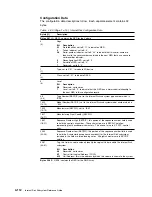
4-30 (Page 5 of 5). Internal Disk Configuration Data
Byte(s)(1)
Description
234
(10)
Not used; set to x'00'
235(5)
(11)
Channel Connection Address; this is the unit address for this volume.
236(5)
(12)
Physical Device ID; this is the same as Channel Connection Address (byte 11
above).
237
(13)
Not Used; set to zeros
238
(14)
System Adapter ID; not used by Internal Disk
239-240
(15-16)
ESCON Link Address; set to zeros by Internal Disk
241(6)
(17)
Interface Protocol Type: set to B
'
01000000
'
to indicate a protocol type of "ESCON
Channel".
242
(18)
NEQ Format
Bit Definition
0
Byte 19 contains the Logical Device ID; set to B
'
1
'
by Internal Disk
1
Bytes 30-31 contain the number of logical paths supported by this subsystem;
set to B
'
0
'
by Internal Disk
2-7
Reserved; set to zeros
243
(19)
Logical Device ID; this is the same as the Channel Connection Address
244-255
(20-31)
Reserved
Notes:
1
Two Byte numbers are shown:
The number not in parenthesis is the byte number within the Configuration Data Record (CDR).
The number in parenthesis is the byte number within the NED/NEQ.
2
Bytes 4-31 are called the node-element identifier and represent a world-wide unique ID for the
Internal Disk volume.
3
Manufacturing Plant Code
This code may not contain the characters
'
I
'
,
'
J
'
,
'
O
'
, or
'
S
'
due to the requirements of the SSD
Serial-Number format.
4 Sequence Number
This five-character sequence number is made up of five alphanumeric characters that may not
contain the letters
'
E
'
,
'
I
'
,
'
J
'
,
'
O
'
,
'
Q
'
,
'
S
'
, or
'
U
'
. In addition, all alpha characters (if any)
must be grouped together in the left-most positions and all numeric characters (if any) must be
grouped in the right-most positions of the 5-character field. These restrictions are imposed due to
the requirements of the SSD Serial-Number format.
5
Byte 11 (Channel Connection Address) and Byte 12 (Physical Device ID) are required by software
to be located at these exact locations in the General NEQ and also that the General NEQ itself be
positioned in bytes 224-255 of the configuration data record.
6
For any channel interface, only one of the bits in this byte may be set to B
'
1
'
; if none are set to
B
'
1
'
, the channel interface type is unspecified.
4-116
Internal Disk Subsystem Reference Guide
Содержание Multiprise 3000
Страница 1: ...S 390 Multiprise 3000 Enterprise Server R IBM Internal Disk Subsystem Reference Guide SA22 1025 00 ...
Страница 2: ......
Страница 3: ...S 390 IBM Internal Disk Subsystem Reference Guide SA22 1025 00 ...
Страница 32: ...2 12 Internal Disk Subsystem Reference Guide ...
Страница 38: ...3 6 Internal Disk Subsystem Reference Guide ...
Страница 182: ...4 144 Internal Disk Subsystem Reference Guide ...
Страница 198: ...5 16 Internal Disk Subsystem Reference Guide ...
Страница 214: ...6 16 Internal Disk Subsystem Reference Guide ...
Страница 234: ...A 10 Internal Disk Subsystem Reference Guide ...
Страница 238: ...B 4 Internal Disk Subsystem Reference Guide ...
Страница 243: ...4 lease the Code or any copy of it Appendix C Warranties C 5 ...
Страница 244: ...C 6 Internal Disk Subsystem Reference Guide ...
Страница 248: ...D 4 Internal Disk Subsystem Reference Guide ...
Страница 254: ...X 6 Internal Disk Subsystem Reference Guide ...
Страница 263: ......
Страница 264: ...IBM Printed in the United States of America on recycled paper containing 10 recovered post consumer fiber SA22 1 25 ...