background image

11148

5

10

11

1

2

3

4

6

7

8

9

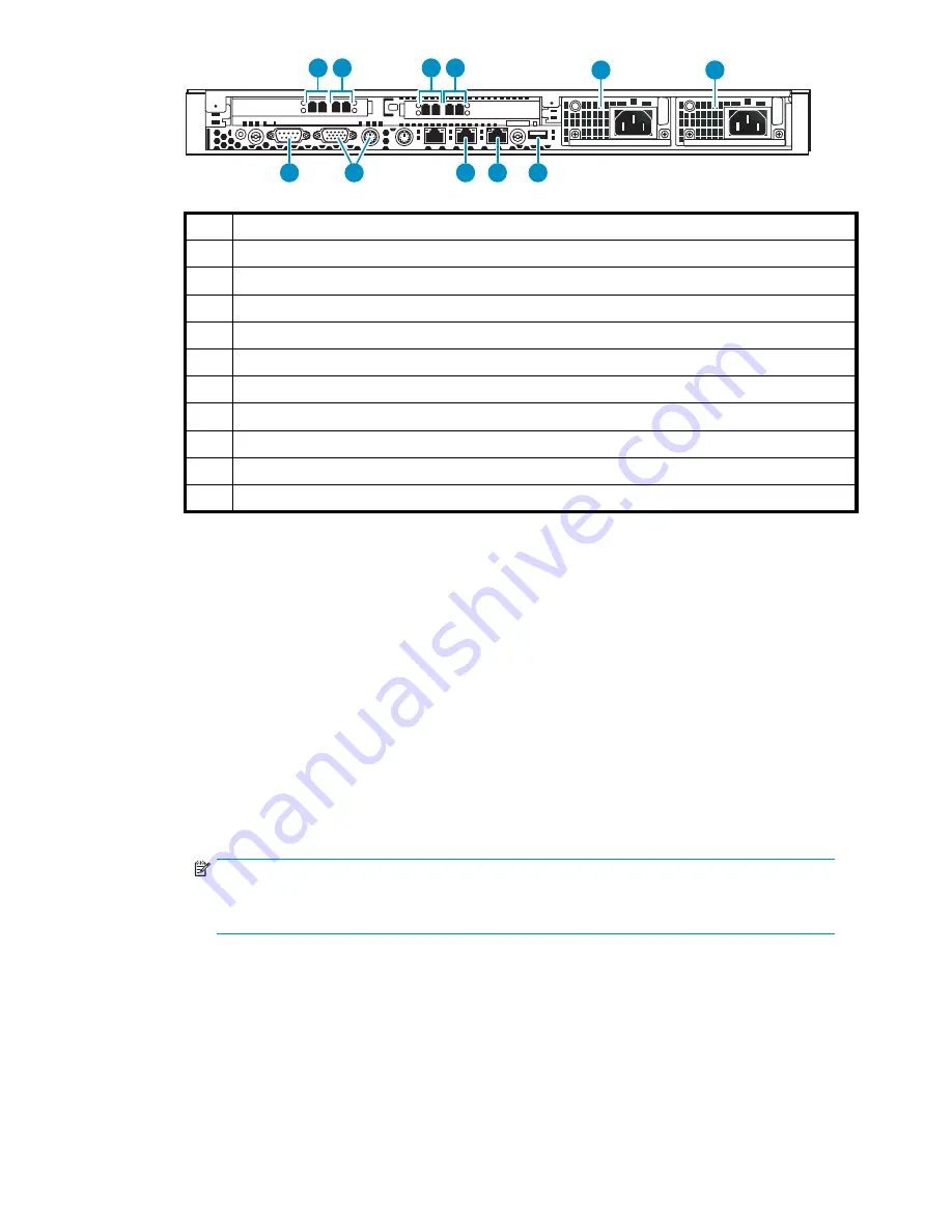
1

Dual port FC card, host port, port 0

2

Dual port FC card, host port, port 1

3

Dual port FC card, storage port, port 3

4

Dual port FC card, storage port, port 2

5

Serial port to access CLI

6

Monitor and keyboard

7

NIC1, on primary node only connects to the customer-provided external network (array)

8

NIC2, on primary node connects to port 1 of switch 2824

9

USB port, connects to USB/Ethernet adapter, then to port 1 of switch 2524

10

Power supply 2

11

Power supply 1

Figure 8 Primary node ports

a.

Connect one end of an Ethernet cable (not included) to NIC1. Connect the other end of the

cable to the existing external network.

b.

Connect one end of an FC cable (not provided) to host port 0. Connect the other end to an

external FC switch/fabric that connects to your tape backup hosts.

c.

If desired, connect one end of an FC cable (not provided) to host port 1. Connect the other end

to an external FC switch/fabric that connects to your tape backup hosts. Otherwise, connect a

loopback plug to host port 1.

d.

Connect one end of an FC cable (not provided) to device port 3. Connect the other end to an

external FC switch/fabric that connects to your external array.

e.

Connect one end of an FC cable (not provided) to device port 2. Connect the other end to a

second external FC switch/fabric that connects to your external array.

f.

Connect to the serial port (cable is provided) to access the command-line user interface at initial

con

fi

guration. Also connect to this during debug activities. Disconnect from this port during

normal operations.

NOTE:

You must connect to the keyboard and monitor ports when performing Quick Restore

(keyboard and monitor not included).

g.

Connect one end of an Ethernet cable to NIC2. Connect the other end of the cable to port

1 of Switch 2824 (see

Figure 10

).

h.

Connect one end of a USB cable to the USB port. Connect the other end of the cable to the

USB/Ethernet adapter. Connect an Ethernet cable to the Ethernet end of the adapter, then

connect the Ethernet cable to port 1 of Switch 2524 (see

Figure 11

).

i.

Connect a power cable to each power supply and to a PDU. If possible, connect each power

supply to a separate PDU to provide redundancy.

HP StorageWorks

31

Содержание StorageWorks 300

Страница 1: ...HP StorageWorks 300 Virtual Library System user guide AH138 96002 Part number AH138 96002 First edition edition November 2006 ...

Страница 2: ...ct to change without notice The only warranties for HP products and services are set forth in the express warranty statements accompanying such products and services Nothing herein should be construed as constituting an additional warranty HP shall not be liable for technical or editorial errors or omissions contained herein ...

Страница 3: ...es 20 Rack requirements 21 Rack warnings 21 Optimum environment 21 Space and airflow requirements 21 Temperature requirements 22 Power requirements 22 Electrical grounding requirements 23 Identifying the shipping carton contents 23 VLS300 system shipping carton 23 Installing the VLS300 nodes into a rack 25 Install rails in the rack 25 Attach rails to the VLS300 appliance 26 Install appliance in ra...

Страница 4: ... interfaces 58 Opening a secure shell session 58 Closing a secure shell session 59 Opening a serial session 59 Closing a serial session 59 7 Configuration 61 Setting the network settings 61 Setting the network settings using the VLS discovery utility 61 Setting the network settings using the CLI command set 63 Setting the network settings using Command View VLS 64 Setting the user preferences 65 E...

Страница 5: ...pport ticket 106 10 CLI command set 107 Commands 107 Conventions 107 CLI only commands 107 Connection commands 107 Output commands 108 VLS commands 108 Network settings configuration commands 108 Configuration commands 109 Management commands 1 14 Monitoring commands 1 15 1 1 Component identification 1 19 VLS300 node components LEDs and buttons 1 19 Front panel components 1 19 Front panel LEDs and...

Страница 6: ...ion 144 Recreating the VLS300 storage pools 145 Re installing the VLS capacity licenses 145 Recovering from operating system failure 145 A Troubleshooting 147 Common issues 147 B Regulatory compliance notices 151 Regulatory compliance identification numbers 151 Battery statement 151 Federal Communications Commission notice 152 FCC rating label 152 Class A equipment 152 Class B equipment 152 Declar...

Страница 7: ...tice 160 Latvian notice 161 Lithuanian notice 161 Polish notice 161 Portuguese notice 162 Slovakian notice 162 Slovenian notice 162 Spanish notice 163 Swedish notice 163 Battery replacement notices 164 Dutch battery notice 164 French battery notice 164 German battery notice 165 Italian battery notice 165 Japanese battery notice 166 Spanish battery notice 166 C Specifications 167 VLS node 167 Switc...

Страница 8: ...down Head Wizard window 49 24 Command View VLS login window 53 25 Security Alert window 55 26 Certificate window 56 27 Certificate Import Wizard window 57 28 Restart Command View VLS window 58 29 VLS discovery utility main window 62 30 VLS discovery utility Device Configuration window 63 31 Set Network Configuration Wizard window 65 32 User Preferences window 66 33 FC Host Ports window 67 34 Chass...

Страница 9: ...fication alert examples 100 66 Notifications window 101 67 Edit Mail Server Settings window 102 68 Edit Email Settings window 103 69 Edit SNMP Settings window 104 70 Log Viewer window 105 71 Support Ticket window 106 72 Sliding the node out of the rack 131 73 Removing a node hard drive 132 74 Ejecting the CD ROM drive 133 75 Removing a node power supply 133 76 Installing an AC power supply 134 77 ...

Страница 10: ... capacity 17 3 VLS user interfaces 51 4 CLI connection commands 107 5 CLI output commands 108 6 CLI network settings configuration commands 109 7 CLI configuration commands 1 10 8 CLI management commands 1 15 9 CLI monitoring commands 1 16 10 ...

Страница 11: ...disaster recovery Troubleshoot configuration problems About this Guide topics include Related documentation Document conventions and symbols Rack stability HP technical support Subscription service Helpful web sites the section called HP authorized reseller Related documentation HP provides the following documentation to support this product HP StorageWorks 300 virtual library system release notes...

Страница 12: ...ext Code variables Command variables Monospace bold text Emphasized monospace text WARNING Indicates that failure to follow directions could result in bodily harm or death CAUTION Indicates that failure to follow directions could result in damage to equipment or data NOTE Provides additional information The following equipment symbols may be found on hardware to which this guide pertains They have...

Страница 13: ...embly marked with these symbols indicates that the component exceeds the recommended weight for one individual to handle safely WARNING To reduce the risk of personal injury or damage to the equipment observe local occupational health and safety requirements and guidelines for manually handling material Rack stability Rack stability protects personnel and equipment WARNING To reduce the risk of pe...

Страница 14: ...fessionals link 4 Click the Driver and Support alerts link 5 Click edit on the Product ownership task bar to add and delete products Subscribing to this service provides you with E mail updates on the latest product enhancements newest driver versions and firmware documentation updates as well as instant access to numerous other product resources Other HP web sites For additional information see t...

Страница 15: ... on a VLS is easily cloned to physical tape for off site disaster protection or long term archival using a backup application Benefits Integrating a VLS into your existing storage and backup infrastructure delivers the following benefits Faster backups Backup speeds are limited by the number of tape drives available to the SAN hosts The VLS emulates many more tape drives than are available in phys...

Страница 16: ...er supplies if one power supply fails in a node the remaining functional power supply provides enough power for the node to function HP recommends that the primary power supplies be connected to a separate power source at the site from the redundant power supplies CAUTION Replace a failed fan or power supply as soon as possible to maximize the life expectancy of the remaining fan s or power supply...

Страница 17: ... to 20 TB Capacity can also be increased by purchasing capacity bundles each of which adds licensing for one additional external array LUN and increases maximum external capacity by up to 2 TB NOTE Maximum capacity for each LUN on the VLS300 is 2 TB Adding nodes and licenses increases the VLS300 storage capacity as shown in Table 2 Adding nodes also increases the performance See the HP StorageWork...

Страница 18: ...18 Introduction ...

Страница 19: ...he design guidelines for example each LUN is roughly the same size 2 TB is preferred The LUNs can not be read only RAID 5 is recommended Path failover is balanced across both EVA controllers If this has not been done refer to the solutions guide for instructions Tools for installation Two people Phillips screwdriver Box cutting knife Taking ESD precautions To prevent damaging the system be aware o...

Страница 20: ...ipping carton for damage that may have occurred during shipment If you detect any damage notify the carrier and HP before unpacking the unit Removing the packing materials To unpack the VLS 1 Open the top of the shipping cartons 2 Carefully lift the units out of the boxes and remove the packing materials 3 Place the units on a stable work surface NOTE Inspect the units for any damage that may have...

Страница 21: ...ng a rack At least two people are needed to safely unload a rack from a pallet An empty 42U rack can weigh as much as 1 15 kg 253 lb can stand more than 2 1 m 7 ft tall and may become unstable when being moved on its casters Never stand in front of a rack when it is rolling down the ramp from the pallet Always handle a rack from both sides Optimum environment When installing a VLS in a rack select...

Страница 22: ...ontinued safe and reliable equipment operation install or position the system in a well ventilated climate controlled environment The maximum recommended ambient operating temperature TMRA for the VLS system is 35 C 95 F The temperature in the room where the rack is located must not exceed 35 C 95 F CAUTION To reduce the risk of damage to the equipment when installing third party options Do not pe...

Страница 23: ...echnical Commission IEC Code 364 parts 1 through 7 Furthermore you must be sure that all power distribution devices used in the installation such as branch wiring and receptacles are listed or certified grounding type devices Because of the high ground leakage currents associated with multiple VLS and servers connected to the same power source HP recommends the use of a power distribution unit PDU...

Страница 24: ... 6 Power cords 6 2 100 Mb Ethernet switch 2524 1 7 Documentation CD 1 and VLS Quick Restore CDs 2 3 1 Gb Ethernet switch 2824 1 8 Printed VLS node installation poster 1 4 3 ft Ethernet cables 5 9 Loopback plugs 5 1U rack mounting hardware kits and documentation 3 10 USB LAN adapters 2 24 Hardware installation ...

Страница 25: ... at the RackSolutions com web site http www racksolutions com hp Follow the instructions on the web site to install the rack brackets To install a node into the rack involves three main tasks Install rails in the rack Attach rails to the VLS appliance Install appliance in rack Install rails in the rack 1 Locate the appropriate rail kit part number 361 190 B21 2 Install the two slide rails to the s...

Страница 26: ...e front of the rack until they lock in place Then press the inner rail release latch see Figure 2 and pull the inner slide rails straight out 10685A Figure 2 Remove slides from rails Attach rails to the VLS300 appliance To attach the rails to the appliance 1 Align the rail with the node so that the word FRONT on the rail is seen right side up and at the front of the node 26 Hardware installation ...

Страница 27: ... appliance fully into the rack The rails on the appliance will lock into the rails on the rack 3 With the appliance fully seated in the rack tighten the thumbscrews just until the node bezel is secured to the rack Install the 100 Mb Ethernet switch 2524 into a rack To install the 100 Mb Ethernet switch 2524 into the rack NOTE There are no rails associated with this switch 1 If the metal mounting b...

Страница 28: ...nt of the switch run the cable through the holes in the rack to the back of the rack but do not connect the cable to a PDU at this time Install the 1 Gb Ethernet switch 2824 into a rack To install a node into the rack involves three main tasks Install rails for switch 2824 in the rack Attach rails to the 2824 switch Install switch 2824 in rack Install rails for switch 2824 in the rack 1 Locate the...

Страница 29: ...w through the rail clip and rack then into the nut Tighten the screw to secure the rail to the rack see Figure 6 e Repeat these tasks for the rail on the other side of the rack Attach rails to the 2824 switch To attach the rails to the 2824 switch 1 Align the inner rail with the switch so that the perpendicular screw hole faces away from the switch but is parallel to the switch bezel face plate Th...

Страница 30: ...tall the other rail on the other side of the node Install switch 2824 in rack 1 Align the rails on the appliance with the rails in the rack 2 Slide the appliance fully into the rack The rails on the appliance will lock into the rails on the rack 3 On each side of the switch insert an MS screw through the holes in the rail and into the holes in the rack 4 Tighten the MS screws to secure the switch ...

Страница 31: ...pback plug to host port 1 d Connect one end of an FC cable not provided to device port 3 Connect the other end to an external FC switch fabric that connects to your external array e Connect one end of an FC cable not provided to device port 2 Connect the other end to a second external FC switch fabric that connects to your external array f Connect to the serial port cable is provided to access the...

Страница 32: ...onnect the other end to an external FC switch fabric that connects to your tape backup hosts Otherwise connect a loopback plug to host port 1 c Connect one end of an FC cable not provided to device port 3 Connect the other end to an external FC switch fabric that connects to your external array d Connect one end of an FC cable not provided to device port 2 Connect the other end to a second externa...

Страница 33: ...IC2 of 6th node if present 7 Ethernet cable from NIC2 of 7th node if present 8 Ethernet cable from NIC2 of 8th node if present 9 Ethernet cable from port 24 of switch 2524 Figure 10 Switch 2824 ports a Ensure that the Ethernet cables from the NIC2 ports of each node are firmly set in the appropriate ports b Connect one end of an Ethernet cable to port 24 of Switch 2824 Connect the other end of the...

Страница 34: ... 1 Switch 2524 ports a Ensure that the power cable is connected to the switch as described in the racking instructions see Installing the VLS node s into a rack b Ensure that the Ethernet cables from the NIC2 ports of each node are firmly set in the appropriate ports on the switch c Ensure that the Ethernet cable from port 24 of Switch 2524 is firmly connected to port 24 of Switch 2824 d Route the...

Страница 35: ...able checks and configuration checks 4 After the checks are complete the node will reboot automatically Wait for the primary node to fully boot Rebooting is complete when you receive the Initializing node then Initializing for node completed messages in the systems notifications if you have DHCP enabled or when you see the login prompt on the terminal Figure 12 Figure 12 Notifications window 5 Set...

Страница 36: ...in the main window This will bring up the Add Node Wizard 10 Verify that the node name in the Node Name field is the next available number that you configured previously Figure 13 For example the primary node previously configured as Node 0 is identified as Node 0 in the list of nodes on the navigation tree The first secondary node added should be Node 1 The next secondary node added should be Nod...

Страница 37: ...rs should also be connected to both zones fabrics If you have not done so refer to the VLS solutions guide to do so now Presenting the LUNs 1 Gather the device WWPNs a From Command View VLS select the System tab b From the Navigation Tree select Nodes then a specific node then Fibre Channel The status pane displays information about the FC ports including the world wide port names WWPNs Figure 14 ...

Страница 38: ...300 and select Linux for the Host OS Figure 15 NOTE If a WWPN is not in the Port WW Name box there may be a zoning error After creating the host entries verify that your zoning is correctly configured Figure 15 Add a Host window e Click on Add Host f From the Storage tab navigation tree select the host you just added g Click on the Ports tab in the status pane h Click on Add port select one of the...

Страница 39: ...t the EVA for the VLS300 storage system Virtual Disks the disk name that you want to present then ACTIVE under that disk b Select the Presentation tab c Ensure that Write Protect is set to No d Ensure that the Preferred path mode is set to either Path A Failover only or Path B Failover only Figure 17 NOTE Set the Preferred path mode for half of the disks to Path A Failover only and to Path B Failo...

Страница 40: ...Ns Delete external LUNs from the VLS300 configuration See Deleting array LUNs Create storage pools See Configuring storage pools Destroy storage pools See Deleting array LUNs Enable device side data compression when creating new tape drives See Creating tape drives Discovering array LUNs 1 Discover the LUNs either by rebooting the entire VLS300 or a Open a Command View VLS session and log in as th...

Страница 41: ...a license violation you can still view all the LUNs Either install more licenses or remove the LUNs that do not belong This will eliminate the violation See Deleting array LUNs Deleting array LUNs To remove a LUN from the device 1 Unpresent the LUN to the VLS see instructions below or delete the LUN from the external array 2 Restart emulations or reboot the device see Restarting the VLS device emu...

Страница 42: ...or detailed instructions CAUTION LUN numbering must be sequential with no gaps Gaps in LUN numbering will prevent the VLS300 from recognizing any nodes with any LUNs after the gap For example if LUN numbering is 0 1 2 4 5 the VLS300 will not recognize LUNs 4 and 5 Configuring storage pools VLS auto creates the first storage pool but you must create any additional pools To do so NOTE The VLS300 can...

Страница 43: ...ommand View VLS session and log in as the administrator See Opening a Command View VLS session from Command View TL b In the Storage tab navigation tree under Storage Pools select a storage pool c From the task bar select Add External LUN The Add External LUN Wizard is displayed NOTE This task does not appear if there are no licenses available d From the list of available unconfigured LUNs select ...

Страница 44: ...w VLS allows you to destroy a specific storage pool or all storage pools NOTE If there are cartridges in the pool or pools when they are destroyed emulations will restart To avoid this restart delete all cartridges from the pool prior to deleting the pool see Destroying cartridges To delete a single storage pool 1 Open a Command View VLS session and log in as the administrator See Opening a Comman...

Страница 45: ...apacity licenses A VLS capacity license must be installed on the VLS when storage exceeds the base license If you are in a license violation state all VLS read write operations are disabled until either sufficient licenses are installed to support the storage or until excess storage is removed Unconfigured VLS300 array LUNs are counted by the system therefore they can contribute to license violati...

Страница 46: ... Make sure to enter the VLS serial number correctly when obtaining the license key If it is entered incorrectly the license key generated will not work and the license registration number will become locked to the wrong serial number If this occurs contact HP Support to obtain a new license registration number 9 Add the license key to Command View TL Command View TL installs the license key on the...

Страница 47: ...tion of their status LEDs 6 Rebooting the system is complete when you receive the Initializing node then Initializing for node completed messages for all nodes in the systems notifications Rebooting the system To reboot the system To reboot from VLS CLI 1 Verify that any backup or restore operation has completed and that the VLS is idle 2 Open a secure shell session and log in as the administrator...

Страница 48: ...n active until AC power is removed To power off the system from the VLS CLI 1 Verify that any backup or restore operation has completed and that the VLS is idle 2 Open a serial session and log in as the administrator See Opening a serial session 3 Initiate a shutdown of the VLS by entering shutdownSystem 4 If you will be removing the access panel from a node wait until the VLS has completed its sh...

Страница 49: ... Wizard window 6 Select Yes to shut down all nodes 7 If you will be removing the access panel from a node wait until the VLS has completed its shutdown operation then press the UID LED button See Front panel LEDs and buttons Blue LEDs illuminate on the front and rear panels of the node 8 Press the Power On Standby button on all nodes to place the nodes in standby mode When a node activates standby...

Страница 50: ...50 Operation ...

Страница 51: ... Explorer 6 0 or higher or Netscape Navigator 4 7 or higher 10 100 1000 BaseT Ethernet port configured with an appropriate IP address host name domain name subnet mask and gateway Can login as Administrator or User See Command View VLS Secure shell ssh Secure shell client such as PuTTY network attached to the VLS node 0 10 100 1000 BaseT Ethernet port configured with an appropriate IP address subn...

Страница 52: ... and saving VLS trace log files Command View VLS is installed on the VLS and communicates through the LAN Users can open a Command View VLS session from a web browser on the LAN HP StorageWorks Command View TL or HP Systems Insight Manager Window regions Command View VLS windows consist of five regions Not all regions are displayed on all windows 1 2 3 4 5 Item Description 1 status banner 2 task b...

Страница 53: ...Sockets Layer SSL certificate install the SSL certificate as described in Installing the SSL certificate into your web browser The first time you open a Command View VLS session and the first time you open a Command View VLS session after changing the fully qualified name of the VLS a Security Alert window opens and prompts you to accept the Secure Sockets Layer SSL certificate Figure 24 Command V...

Страница 54: ...ur web browser The first time you open a Command View VLS session and the first time you open a Command View VLS session after changing the fully qualified name of the VLS a Security Alert window opens and prompts you to accept the Secure Sockets Layer SSL certificate 4 Enter administrator or user in the Username box The username is case sensitive NOTE Logging in as administrator gives you full pr...

Страница 55: ...Figure 25 Security Alert window 2 Click Install Certificate and then click OK HP StorageWorks 55 ...

Страница 56: ...Figure 26 Certificate window 3 Select Automatically select the certificate store based on the type of certificate and then click Next 56 User interfaces ...

Страница 57: ...dow that displays until the Command View VLS login window displays Restarting Command View VLS To restart Command View VLS 1 Under the System tab select Chassis in the navigation tree 2 Under Maintenance Tasks select System Maintenance 3 Click Restart Command View VLS in the task bar The Restart Command View VLS window opens Figure 28 HP StorageWorks 57 ...

Страница 58: ...LS network settings Configuration and management of VLS virtual devices libraries and tape drives and cartridges Changing of the default FC host port settings Viewing and deleting VLS notification alerts Configuring VLS mail and SNMP notification alert settings Editing VLS account passwords Enabling and disabling storage capacity oversubscription Viewing VLS hardware status Saving and restoring VL...

Страница 59: ... a PC or workstation to the serial connector on the rear of node 0 of the VLS using the null modem serial cable provided See Rear panel components 2 Establish a CLI session using a terminal emulation program such as Windows Hyperterminal 3 Enter administrator or emergency for username 4 Enter the password for the username entered The default administrator password is admin The emergency login pass...

Страница 60: ...60 User interfaces ...

Страница 61: ...e devices on the same subnet as the Windows computer on which it is running It then lists the devices and indicates whether they are configured have an IP address or unconfigured You can use the VLS discovery utility to set the network settings on an unconfigured VLS and to view the network settings of configured devices The utility can also be used to remove LUNs from the user interface after one...

Страница 62: ...main window 3 Optional To visually identify a device listed select the device from the list and click Beacon This will illuminate an LED on the device for the specified length of time In the case of the VLS the UID LED button on the VLS node illuminates See Front panel LEDs and buttons 4 Select the VLS from the list of devices and click Configure The Device Configuration window opens Figure 30 62 ...

Страница 63: ...indow on the computer running the VLS discovery utility and type ipconfig all 8 Enter the gateway in the Gateway box 9 Enter the DNS server IP address in the DNS IP Address box 10 Enter the domain name in the Domain Name box 1 1 Click Configure to save the network settings to the VLS 12 Click Exit to close the VLS discovery utility Setting the network settings using the CLI command set To set the ...

Страница 64: ...ress of public Ethernet connection gate Gateway to network xx xx xx x mask Netmask Default is 255 255 255 0 NOTE More than one network value can be set at a time or you can set them individually To reset a value enter quoted space as the value 4 Verify the network setting s has been changed by entering showConfig 5 When all the network parameters are set to your desired values save the settings by...

Страница 65: ...hich the system state is checked and the browser is refreshed Add the VLS administrator s name company mail and phone number and the VLS location to the Identity tab window Set the maximum number of notification alerts to store To set the user preferences 1 Open a Command View VLS session and log in as the administrator See Opening a Command View VLS session from Command View TL 2 From the System ...

Страница 66: ... are unable to log in to Command View VLS 1 1 Click Apply Settings Editing the default FC host port settings Only edit the FC host port settings if you do not want to use the default settings if some system problem is occurring or if the AUTO setting is not working properly NOTE The values displayed under Actual are the actual values found by the VLS for the FC host port NOTE If you enter a value ...

Страница 67: ...in the Link Speed Preferred box for each FC host port Auto Allows the VLS to determine the FC port s link speed 1 1 GB per second 2 2 GB per second 9 When you are finished configuring the FC ports click Apply Settings 10 Restart the VLS device emulations to make the changes take effect See Restarting the VLS device emulations Enabling and disabling oversubscription Because the VLS dynamically allo...

Страница 68: ...device to a specific FC host port These features allow you to allocate the virtual devices to individual hosts and distribute the virtual tape drives across the FC host ports to achieve maximum bandwidth See Managing high availability for more information By default the VLS allows all hosts connected to the VLS through the SAN to access all virtual devices configured on the VLS Also the VLS softwa...

Страница 69: ...evices on that port If the operating system sees a LUN0 LUN1 and LUN2 but not a LUN3 on the port it will stop looking for LUNs on that port when the gap in the LUN numbering is encountered Even though there may be more LUNs such as LUN4 the operating system will erroneously report that there are only three LUNs on the port In addition operating systems are configured to only look for a maximum num...

Страница 70: ...t name in the Hostname box 7 To add a host WWPN to the list that is not plugged into the SAN yet enter the host WWPN number and then click Add 8 When you are finished making changes click Apply Settings LUN mapping By default all hosts on the SAN see the LUN numbers that have been assigned to the virtual devices by the VLS software You have the option of assigning a different LUN number to a virtu...

Страница 71: ...n the VLS that you want to make visible to the host CAUTION Each virtual device must be assigned a unique LUN number on the FC host port to which it is mapped If two virtual devices have the same LUN number on the same FC host port the virtual device with the lowest virtual device ID number assigned by the VLS is recognized as that LUN number by the host s operating system The other virtual device...

Страница 72: ... for your environment See the HP StorageWorks 300 Virtual Library System solutions guide You can configure any combination of virtual tape libraries and virtual tape drives up to the maximum number supported on the VLS You can configure one node with up to 16 libraries with a total of up to 128 tape drives With multiple nodes a single library can span across nodes To create a new virtual library 1...

Страница 73: ...ximum Slots box is based on the physical tape library you selected CAUTION Changing the defaults can have unpredictable results if your backup application expects a certain number of slots in a specific library type 9 Enter the maximum number of input export ports on which the library may be configured to be visible in the Maximum Ports box 10 Enter the maximum number of tape drives the library ma...

Страница 74: ... 13 Choose one of the following options To perform LUN mapping for the virtual library click Map LUNs and proceed to LUN mapping for further instructions To continue creating the virtual library click Create Tape Drive s and proceed to Creating tape drives To exit the wizard click Cancel The library is created but does not contain any tape drives or cartridges You can add tape drives and cartridge...

Страница 75: ... of tape drive To add a tape drive s to a virtual library 1 If you are already in the Create Library Wizard window click Create Tape Drive s The Tape Drive Parameters window opens 2 If not a Click the System tab b Select the library in the navigation tree to which you want to add tape drives c Click Create Tape Drive in the task bar The Tape Drive Parameters window opens Figure 41 Figure 41 Create...

Страница 76: ...alance the tape drives across the FC host ports to obtain maximum performance Tape drives in a library do not have to be mapped to the same port as the library 7 To enable data compression for the tape drive s select Enable Compression Data compression 2 1 is performed only on data handled by tape drives with data compression enabled Data compression allows the VLS to store more data NOTE A tape d...

Страница 77: ...wizard click Cancel At this point the library and tape drives have been created but the library does not contain any cartridges You can add cartridges later Creating cartridges To add cartridges to a virtual library 1 If you are already in the Create Library Wizard window Figure 43 click Create Cartridges The Cartridge Parameters window opens Figure 44 2 If not a Click the System tab b Select the ...

Страница 78: ...x d Enter the starting barcode number in the Starting box e Click Add to add the new barcode template f To add another barcode template repeat these steps 4 Click the radio button next to the barcode template you want to use to create the cartridges NOTE Select a six character or less barcode number if your backup application is Veritas Netbackup Veritas Netbackup has a six character barcode numbe...

Страница 79: ...e pool in which to create cartridges from the Available capacity drop down box The system calculates and displays the amount of required storage If the required storage exceeds what is available the overage appears in red You can allow the oversubscription of storage capacity see Enabling and disabling oversubscription or you can change either the number of cartridges or the cartridge size or both...

Страница 80: ...uration information such as their default LUN numbers Destroying a virtual library NOTE Destroying a virtual library may create a gap in the default LUN numbering on the FC host port to which it was mapped If a gap is created restart the VLS device emulations to remove the gap See Restarting the VLS device emulations Most operating systems will ignore cannot access any virtual devices with LUN num...

Страница 81: ...w TL 2 Click the System tab 3 Select the virtual library in the navigation tree The virtual library details window opens Figure 49 Figure 49 Virtual library details window 4 Click Destroy Virtual Library in the task bar 5 Click Yes to confirm 6 Click Finish Destroying a tape drive NOTE Destroying a tape drive may create a gap in the default LUN numbering on the FC host port to which it was mapped ...

Страница 82: ...ish Destroying cartridges CAUTION If you want to keep data that is currently on a cartridge that you are going to delete copy the data to another cartridge using a backup application before performing this task NOTE You cannot destroy a cartridge that is currently being accessed by a backup application To destroy cartridges 1 Open a Command View VLS session and log in as the administrator See Open...

Страница 83: ...om the drop down box beside the group of cartridges you wish to destroy Options are 10 50 100 default 500 or 1024 cartridges 5 Click the View button beside the category that contains the cartridge s you want to delete The cartridges parameters window opens Figure 52 HP StorageWorks 83 ...

Страница 84: ...th the appropriate values to use the barcode number s Delete the barcode template used to create the original cartridge s and then recreate the barcode template with the appropriate values to use the barcode number s Adding and removing barcode templates You can add and remove delete but not edit cartridge barcode templates at any time NOTE Deleting a barcode template does not affect the cartridge...

Страница 85: ...e The window refreshes when the deletion operation is finished 6 To add a barcode template a Enter the barcode prefix one to five alpha characters in the Barcode Prefix box b Enter the number of digits for the barcode number in the Digit Length box c Enter the barcode suffix one to two alpha characters in the Barcode Suffix box d Enter the starting barcode number in the Starting box e Click Add to...

Страница 86: ...86 Configuration ...

Страница 87: ...ser account password 1 Open a Command View VLS session and log in as the administrator See Opening a Command View VLS session from Command View TL 2 On the System tab select Chassis from the navigation tree 3 Click Edit Accounts under Maintenance Tasks The Edit Accounts window opens Figure 54 Figure 54 Edit Accounts window 4 Enter the current password in the Old Password box The password is case s...

Страница 88: ...r from a specific node through a fabric to the external array is conducted over one path half over a second fabric hence another path The paths are selected as follows Once configured the device recognizes all paths to each node on the device From all potential preferred paths and all potential secondary paths see Step 3 the array assigns one preferred path and one secondary path NOTE During each ...

Страница 89: ...t bus number always 0 the target id an EVA port and the LUN number on the EVA When one path fails automatic failover reroutes data traffic to the secondary path so the data transfer still happens but potentially at a slower rate It is advised that you restore the path as soon as possible to avoid a double path failure To restore the failed path 1 Determine the cause of the failure and repair it if...

Страница 90: ...nn numerical wwnn A double path failure that occurs upon booting the system results in the critical alert Missing Storage LUN paths on node This means the node can not communicate with the LUN at all If the failed paths are on the primary node the whole storage pool containing that LUN is off line if the failed paths are on a secondary node the storage pool is on line until reboot but the storage ...

Страница 91: ...itch associated with NIC2 fails the Notifications tab will display all eth1 failures The secondary path is through the USB LAN cable and is identified as eth2 in the error notification If the LAN switch associated with the USB LAN cable fails the Notifications tab will display all eth2 failures If both paths fail the critical alert will identify bond 0 as the combined failed path If both paths fro...

Страница 92: ...to edit Options are 10 50 100 default 500 or 1024 cartridges 5 Click the View button beside the group of cartridges you want to edit If viewing by barcode enter a cartridge range to view a specific cartridge s or leave the default values to view all the cartridges with the barcode The Cartridges Parameters window opens Figure 59 92 Management ...

Страница 93: ...ove selected to box c Click the Go button next to the Move selected to box 7 To change a cartridge s total capacity a Select the Select box next to each cartridge that you want to edit b Enter a new value in GB in the Total box c Click Update 8 To change a cartridges read and write access a Select the Select box next to each cartridge that you want to edit b Select the desired access from the Acce...

Страница 94: ...ges in a virtual library will not free up disk space Storage space is dynamically assigned by the VLS as it is used It is not reserved Restarting VLS device emulations Restart VLS device emulations If the VLS locks up After destroying a virtual device library or tape drive on the VLS and doing so leaves a gap in the virtual device LUN numbering on an FC host port After adding a virtual tape drive ...

Страница 95: ...ck Chassis in the navigation tree 3 Click on System Maintenance under Maintenance Tasks 4 Click Restart Emulations in the task bar The Restart Emulations window opens Figure 60 Figure 60 Restart Emulations window 5 Click Restart Emulations to confirm Updating the software CAUTION The VLS restarts automatically when a software update is installed To update the VLS software 1 Obtain the VLS software...

Страница 96: ...AN It does this by generating a VLS serial number and FC port WWPNs at first boot which are based on the system board s MAC address The VLS serial number and FC port WWPNs are saved on the VLS hard drives and with the virtual library configuration settings in the configuration file HP highly recommends that you save your virtual library configuration and the VLS network settings to an external con...

Страница 97: ...e File name box 6 Click Save wait for the file to finish downloading and then click Close The Save Configuration window re opens 7 Click Finish NOTE Optionally you can set the device to automatically save and E mail the configuration file at midnight after the configuration is modified See Edit the E mail settings HP StorageWorks 97 ...

Страница 98: ...98 Management ...

Страница 99: ...is inoperable Immediate service is needed Missing The VLS cannot detect the component or a part of the component In addition to the device status a red or yellow alert bar will highlight specific parts of a component when that particular element within the component has failed red or is operating outside its normal range yellow To view the status information for a VLS hardware component or virtual...

Страница 100: ...on tree when an unknown warning or error condition is present with a component It also appears just to the left of the parent objects of that component For example if the icon is displayed by Fibre Channel in the navigation tree it will also be displayed by its parent objects for example Node 0 Nodes and Chassis Figure 64 Navigation tree icon Notification alerts If a VLS hardware component or an e...

Страница 101: ...ion alert to view more information about the notification alert To view the notification alerts for a specific VLS hardware component 1 Open a Command View VLS session See Opening a Command View VLS session from Command View TL 2 Click the System tab 3 Select the object in the navigation tree that represents the hardware component that you want to view The notification alerts relevant to the objec...

Страница 102: ...ssion from Command View TL 2 Click the Notifications tab The Notifications window displays Figure 66 3 Click Edit Mail Server Settings in the task bar The Edit Mail Server Settings window opens Figure 67 Figure 67 Edit Mail Server Settings window 4 To add a mail server a Enter the domain name for a mail server with an SMTP gateway that will process mail from the VLS in the Outgoing Mail Server box...

Страница 103: ...il Settings window opens Figure 68 Figure 68 Edit Email Settings window 4 To add an E mail address a Enter an E mail address in the Email Address box b Select the type of notification alerts to send in the Alerts box All Sends all notifications Errors Sends only errors Warnings Sends only warnings None Sends no notifications c Select a notification alert format in the Format box Short Sends short ...

Страница 104: ...VLS session from Command View TL 2 Click the Notifications tab The Notifications window displays Figure 66 3 Click Edit SNMP Setting in the task bar The Edit SNMP Settings window opens Figure 69 Figure 69 Edit SNMP Settings window 4 To add management consoles a Enter the host name of a management console that you want to receive VLS SNMP traps in the Hostname box b Enter the string name that is pa...

Страница 105: ...Command View TL 2 Click the System tab 3 Select Chassis in the navigation tree 4 Click Log Viewer under Maintenance Tasks The Log Viewer window opens Figure 70 Figure 70 Log Viewer window 5 Click the trace log file that you want to view The contents of the trace log file opens Saving a trace log file To save a trace log file to an external file 1 Log in to Command View VLS as the administrator See...

Страница 106: ...tor or user 2 Click the System tab 3 Select Chassis in the navigation tree 4 Click Support Ticket under Maintenance Tasks The Support Ticket window opens Figure 71 Figure 71 Support Ticket window 5 Right click Download Support Ticket package 6 Select Save Target As The name of a zip file is displayed in the File name box 7 Click Save 8 Click Close 9 Click Finish 106 Monitoring ...

Страница 107: ... used in this section to identify option tags and arguments An option tag is preceded by either The argument is separated from the option tag by a space If an argument contains a space it must be enclosed by either two single quotes or two double quotes If there is no argument after an option tag the option is a switch An after an argument means the argument including its option tag can be repeate...

Страница 108: ...lso help Displays CLI command usage information Where tag can be c command Provides help information for the specified CLI command all Lists all CLI commands and their help information VLS commands This section describes the VLS commands in the VLS CLI command set Network settings configuration commands Use the CLI commands in to configure the VLS network settings via a serial session See Opening ...

Страница 109: ...th dnsaddr dhcp Has no value indicates you want to configure the public Ethernet connection using DHCP reset is dhcp false ipaddr IP address of public Ethernet connection gate Gateway to network xx xx xx x mask Netmask Defaults to 255 255 255 0 getDateTime Displays the day date time time zone and year such as Mon March 14 1 1 30 46 EST 2005 setDateTime d s Sets the date and time Enter date and tim...

Страница 110: ... is enabled or disabled and the capacity remaining percentage for notification alert Oversubscription is enabled when enabled 0 Oversubscription is disabled when enabled 1 getLunMap Returns existing LUN mapping configured on the VLS for the LUN specified Where the options are a n Number of the node 0 required l n LUN number of device whose LUN map you wish to view required h Displays command usage...

Страница 111: ...ptions are a n Node ID of node on which the tape drive emulation will reside 0 required c n Data compression 0 Disabled 1 Enabled required l n LUN number to assign to tape drive 1 to 128 optional la n Node number on which the library emulation of the library to associate with the tape drive s resides 0 to 3 required ll n LUN number of library with which to associate tape drive 0 1 required n n Num...

Страница 112: ...eated with this template 1 to 1024 required u n Barcode suffix length Number of digits for cartridge sequencing 1 to 16 required h Displays command usage information optional getBarCodes Returns a list of all the barcode templates and their settings that have been defined Displays each barcode template s name prefix start index and suffix length deleteBarCode Deletes the specified barcode template...

Страница 113: ...d l s Library name Library_0 required n n Number of cartridges required ov n Oversubscribe 0 or 1 required u n Barcode suffix length required y n Cartridge type 2 required h Displays command usage information optional getCartridges Returns a list of the cartridges that have been created All cartridges have both a VLS filename cartridge name and a barcode label This command returns the following ca...

Страница 114: ...r data from the VLS Where the options are a s VLS filename of cartridge to delete required b s Barcode value of cartridge to delete required c n Capacity of cartridge to delete in gigabytes required f Force Do the remove without a prompt optional l s Name of library with which cartridge is associated Library_0 required h Displays command usage information optional getStorageCapacity Returns the to...

Страница 115: ...d nc n Desired new capacity of the cartridge in gigabytes optional nl s Name of the new library if moving cartridge Library_1 optional w Write protect 0 read write or 1 read only optional y n Cartridge emulation type 2 3 required h Displays command usage information optional restartEmulations Restarts the VLS device emulations restartCommandViewVLS Restarts Command View VLS restartSystem Shuts dow...

Страница 116: ...command usage information optional getNotificationsDate Returns all the notification alert messages that occurred starting with the specified date Where the options are d mm dd yy on or after this date required h Displays command usage information optional deleteNotifications Deletes the specified notification alerts from the VLS Where the options are id s ID number of notification to delete requi...

Страница 117: ...address required c s VLS node IP address required f Force Do the delete without a prompt optional h Displays command usage information optional addSnmpServer Specifies an SNMP management console to receive SNMP traps from the VLS Where the options are a s SNMP server IP address required c s VLS node IP address required m s Community Public required v s Trap version required h Displays command usag...

Страница 118: ...1 18 CLI command set ...

Страница 119: ...riptions of the node LEDs and buttons VLS300 node components LEDs and buttons Front panel components 1 2 5 4 3 Item Description 1 Diskette drive blank 2 CD ROM drive 3 Front USB port 4 Hard drive 0 5 Hard drive 1 Front panel LEDs and buttons 1 2 3 4 5 6 HP StorageWorks 1 19 ...

Страница 120: ...to system board LEDs Off System health is normal when in standby mode 4 External health LED power supply Green Power supply health is normal Amber Power redundancy failure occurred Off Power redundancy failure has occurred When the node is in standby mode power supply health is normal 5 NIC 1 link activity LED Green Network link exists Flashing green Network link and activity exist Off No link to ...

Страница 121: ... port 2 5 Serial port to access CLI 6 Monitor and keyboard 7 NIC1 on primary node only connects to the customer provided external network array 8 NIC2 on primary node connects to port 1 of switch 2824 9 USB port connects to USB Ethernet adapter then to port 1 of switch 2524 10 Power supply 2 1 1 Power supply 1 System board components 1A 2A 3B 4B 1 2 4 6 7 8 12 13 14 10 5 3 11 9 HP StorageWorks 121...

Страница 122: ...7 CD ROM drive connector 14 System board battery System board LEDs 3 4 5 6 7 8 9 10 11 12 13 14 15 1 2 Item Description Status 1 DIMM 4B failure Amber DIMM has failed Off DIMM is operating normally 2 DIMM 3B failure Amber DIMM has failed Off DIMM is operating normally 3 DIMM 2A failure Amber DIMM has failed Off DIMM is operating normally 4 DIMM 1A failure Amber DIMM has failed Off DIMM is operatin...

Страница 123: ...le has failed Red Multiple fans in this module have failed Off All fans in this module are operating normally 13 System diagnostic Refer to the HP Remote Lights Out Edition II User Guide 14 Online spare memory Amber Failover has occurred Online spare memory is in use Green Online spare memory is enabled but not in use Off Online spare memory is disabled 15 Riser interlock Amber PCI riser assembly ...

Страница 124: ... slot X is in a pre failure condition DIMM in slot X is an unsupported type but valid memory exists in another bank DIMM failure all slots in one bank Amber Red No valid or usable memory is installed in the system Amber The Health Driver has detected a cautionary temperature level Overtemperature Amber Red The node has detected a hardware critical temperature level Riser interlock Amber Red The PC...

Страница 125: ...ly zone fan module fan 1 2 Processor zone fan module fan 2 Processor zone fan module LED Description Amber One fan in this module has failed Red Multiple fans in this module have failed Off All fans in this module are operating normally HP StorageWorks 125 ...

Страница 126: ...pter on 7th node 8 Ethernet cable from USB adapter on 8th node 9 Ethernet cable from port 24 of switch 2824 Switch 2824 components 11147 1 3 5 7 2 4 6 8 9 Item Description 1 Ethernet cable from NIC2 of primary node 2 Ethernet cable from NIC2 of 3rd node 3 Ethernet cable from NIC2 of 5th node 4 Ethernet cable from NIC2 of 7th node 5 Ethernet cable from NIC2 of 2nd node 6 Ethernet cable from NIC2 of...

Страница 127: ...USB LAN adapter components 11191 1 2 3 Item Description 1 USB LAN adapter 2 LAN cable 3 USB cable HP StorageWorks 127 ...

Страница 128: ...128 Component identification ...

Страница 129: ...a grounded surface before removing them from their containers Avoid touching pins leads or circuitry Always be properly grounded when touching a static sensitive component or assembly Grounding methods to prevent electrostatic damage There are several methods for grounding Use one or more of the following methods when handling or installing electrostatic sensitive parts Use a wrist strap connected...

Страница 130: ...nts For more information about telco rack solutions see the RackSolutions com web site http www racksolutions com hp Power off the system See Powering off the system If you must remove a non hot plug component from the node power off the system Remove the node access panel See Removing the VLS node access panel If you must remove a component located inside the node remove the access panel Extendin...

Страница 131: ...TION Do not operate the node for long periods without the access panel Operating the node without the access panel results in improper airflow and improper cooling that can lead to thermal damage CAUTION Electrostatic discharge can damage electronic components Properly ground yourself before beginning any installation procedure 1 Power off the node See Powering off the system 2 Extend the node fro...

Страница 132: ... RAID to mirror the two drives the node cannot boot up from drive 1 a bootable drive must be installed in drive bay 0 To replace drive 0 remove drive 0 remove drive 1 install previous drive 1 into drive bay 0 then install the new blank drive into drive bay 1 To replace the component 1 Pull out the latch handle out as far as it can go and slide the drive into the bay until the latch mechanism engag...

Страница 133: ... 1 Carefully align the connector on the rear of the drive with the connector on the CD ROM diskette drive interface board 2 Slide the drive into the bay until it clicks Power supply CAUTION To prevent improper cooling and thermal damage do not operate the node unless all bays are populated with either a component or a blank 1 Disconnect the power cord from the power supply 2 Press the power supply...

Страница 134: ...e strain relief clip 4 Connect the power cord to the power supply 5 Be sure that the power supply LED is green Power supply zone fan module CAUTION Do not operate the node for long periods without the access panel Operating the node without the access panel results in improper airflow and improper cooling that can lead to thermal damage 1 Power off the node See Powering off the system 2 Extend or ...

Страница 135: ...r zone fan module CAUTION Do not operate the node for long periods without the access panel Operating the node without the access panel results in improper airflow and improper cooling that can lead to thermal damage 1 Extend or remove the node from the rack See Extending the node from the rack 2 Remove the access panel See Removing the VLS node access panel 3 Loosen the single thumbscrew that sec...

Страница 136: ...l 4 Open the DIMM slot latches 1 5 Remove the DIMM 1 1 2 Figure 80 Removing the node DIMM CAUTION Use only Compaq branded or HP DIMMs DIMMs from other sources may adversely affect data integrity To replace the component reverse the removal procedure NOTE DIMMs do not seat fully if turned the wrong way When replacing a DIMM align the DIMM with the slot and insert the DIMM firmly pressing down until...

Страница 137: ...nk and retaining clip make up a single assembly CAUTION To prevent possible node malfunction and damage to the equipment replace the processors with the same make and type of processor To remove a processor 1 Power off the node See Powering off the system 2 Extend the node from the rack See Extending the node from the rack 3 Remove the access panel See Removing the VLS node access panel 4 Rotate t...

Страница 138: ...rotective cover from the processor Figure 83 Figure 83 Removing the protective cover from the processor 2 Align the holes in the heatsink with the guiding pegs on the processor cage Figure 84 CAUTION To prevent possible node malfunction or damage to the equipment be sure to align the processor pins with the corresponding holes in the socket 138 Component replacement ...

Страница 139: ...l See Installing the VLS node access panel 6 Slide the node into the rack 7 Power on the node See Powering on the VLS300 system Replacing a primary node CAUTION Each VLS300 node weighs 16 78 kg 37 lb full At least two people are required to lift and move each node To replace a primary node 1 Remove the existing node from the rack a Power off the system See Powering off the system b From the back o...

Страница 140: ...g 37 lb full At least two people are required to lift and move each node To replace a primary node 1 Remove the existing node from the rack a Power off the system See Powering off the system b From the back of the node make a note of all cable connections then disconnect the cables c From the front of the node loosen the captive thumbscrews until the thumbscrews are free of the rack d Pull the nod...

Страница 141: ... switch then disconnect the cables 3 From the front of the node loosen the captive thumbscrews until the thumbscrews are free of the rack 4 Pull the switch out from the rack until it stops 5 Squeeze the release brackets then pull the node free from the rails 6 Install the new switch into the rack See Install the 1 Gb Ethernet switch 2824 into a rack 7 Reconnect all cables to the new switch exactly...

Страница 142: ...142 Component replacement ...

Страница 143: ... capacity licenses Restoring the configuration settings The VLS virtual library configuration and network settings can be quickly restored from the configuration file created by performing Saving configuration settings See Restoring the virtual library configuration from a configuration file If a configuration file was not created you must reconfigure the network settings and rebuild the virtual l...

Страница 144: ...ig window opens Figure 87 Figure 87 Restore Config window 6 Click Browse 7 Locate and select the desired configuration file 8 Click Open 9 Click Next Step A message is displayed indicating that the file was uploaded successfully 10 Click Next to start loading the configuration file After the configuration file is loaded the system automatically applies the configuration and reboots Rebuilding the ...

Страница 145: ...ly assigned This is also described in Configuring storage pools CAUTION Do not use the Format checkbox option This will destroy all existing cartridges in that pool Re installing the VLS capacity licenses If one or more capacity bundles or existing disk arrays were added to the VLS re install the VLS capacity license s using Command View TL NOTE See the HP OpenView Command View for TL User Guide f...

Страница 146: ... 4 Press R on the keyboard to start the re installation The re installation takes 30 minutes or less to complete The screen may freeze during the last 10 minutes of the re installation This is normal The VLS Quick Restore CD is ejected and the system reboots when the re installation is complete 5 When restoring the primary node restore the configuration settings See Restoring the configuration set...

Страница 147: ...re to restrict the number of virtual devices the host sees on the VLS FC host port s so it only sees the virtual devices it needs to see Then use the VLS s LUN mapping feature to assign LUNs to the virtual devices the host can see such that the virtual device LUN numbers include a LUN0 and no gaps in the LUN numbering See LUN masking and LUN mapping for instructions Some of the virtual devices are...

Страница 148: ... and unplug all FC cables 2 Delete all files and folders under the system32 NtmsData folder location of the system32 folder varies from Windows versions 3 In the Microsoft Computer Management window enable and start the RSM 4 Bring up the Removable Storage utility in the Microsoft Computer Management window 5 Verify there are no Tape or Library devices listed other than the direct attached devices...

Страница 149: ...tion alerts for each FC host port are generated indicating the FC ports are operating normally This is expected behavior and does not indicate a problem None After replacing drive 0 in a node the system will not boot A blank drive was installed in drive bay 0 If a blank drive is installed in drive bay 0 the system will not boot To remedy this switch the drive located in bay 0 with the drive locate...

Страница 150: ...150 Troubleshooting ...

Страница 151: ...nt WARNING This product contains one lithium manganese dioxide a vanadium pentoxide or an alkaline battery and four nickel metal hydride NiMH battery packs The disk array controller module contains two nickel metal hydride NiMH battery packs HP P N 307132 001 Lithium may be considered a hazardous material Dispose of these batteries in accordance with local state and federal laws In addition Do not...

Страница 152: ...ference to radio communications Operation of this equipment in a residential area is likely to cause harmful interference in which case the user will be required to correct the interference at personal expense Class B equipment This equipment has been tested and found to comply with the limits for a Class B digital device pursuant to Part 15 of the FCC Rules These limits are designed to provide re...

Страница 153: ... brouilleur du Canada Class B equipment This Class B digital apparatus meets all requirements of the Canadian Interference Causing Equipment Regulations Cet appareil numérique de la class B respecte toutes les exigences du Règlement sur le matériel brouilleur du Canada European Union notice Products bearing the CE marking comply with the EMC Directive 89 336 EEC and the Low Voltage Directive 73 23...

Страница 154: ...Japanese notices Japanese power cord statement Korean notices Class A equipment Class B equipment 154 Regulatory compliance notices ...

Страница 155: ...s installation guide may result in hazardous radiation exposure To reduce the risk of exposure to hazardous radiation Do not try to open the module enclosure There are no user serviceable components inside Do not operate controls make adjustments or perform procedures to the laser device other than those specified herein Allow only HP Authorized Service technicians to repair the unit The Center fo...

Страница 156: ...Seuls les Mainteneurs Agréés HP sont habilités à réparer l appareil laser German laser notice VORSICHT Dieses Gerät enthält möglicherweise einen Laser der nach den US amerikanischen FDA Bestimmungen und nach IEC 60825 1 als Laserprodukt der Klasse 1 zertifiziert ist Gesundheitsschädliche Laserstrahlen werden nicht emittiert Die Anleitungen in diesem Dokument müssen befolgt werden Bei Einstellungen...

Страница 157: ...ione di quelle specificate da queste istruzioni Affidare gli interventi di riparazione dell unità esclusivamente ai tecnici dell Assistenza autorizzata HP Japanese laser notice Spanish laser notice ADVERTENCIA Este dispositivo podría contener un láser clasificado como producto de láser de Clase 1 de acuerdo con la normativa de la FDA de EE UU e IEC 60825 1 El producto no emite radiaciones láser pe...

Страница 158: ...our household waste disposal service or the shop where you purchase the product Dutch notice Verwijdering van afgedankte apparatuur door privé gebruikers in de Europese Unie Dit symbool op het product of de verpakking geeft aan dat dit product niet mag worden gedeponeerd bij het normale huishoudelijke afval U bent zelf verantwoordelijk voor het inleveren van uw afgedankte apparatuur bij een inzame...

Страница 159: ...a collecte et le recyclage de vos appareils mis au rebut indépendamment du reste des déchets contribue à la préservation des ressources naturelles et garantit que ces appareils seront recyclés dans le respect de la santé humaine et de l environnement Pour obtenir plus d informations sur les centres de collecte et de recyclage des appareils mis au rebut veuillez contacter les autorités locales de v...

Страница 160: ...ecchiature consegnandole presso un punto di raccolta designato al riciclo e allo smaltimento di apparecchiature elettriche ed elettroniche La raccolta differenziata e il corretto riciclo delle apparecchiature da smaltire permette di proteggere la salute degli individui e l ecosistema Per ulteriori informazioni relative ai punti di raccolta delle apparecchiature contattare l ente locale per lo smal...

Страница 161: ...Latvian notice Lithuanian notice Polish notice HP StorageWorks 161 ...

Страница 162: ...coleta para reciclagem A coleta e a reciclagem seletivas desse tipo de lixo ajudarão a conservar as reservas naturais sendo assim a reciclagem será feita de uma forma segura protegendo o ambiente e a saúde das pessoas Para obter mais informações sobre locais que reciclam esse tipo de material entre em contato com o escritório da HP em sua cidade com o serviço de coleta de lixo ou com a loja em que...

Страница 163: ...ciclado póngase en contacto con su ayuntamiento con el servicio de eliminación de residuos domésticos o con el establecimiento en el que adquirió el producto Swedish notice Bortskaffande av avfallsprodukter från användare i privathushåll inom Europeiska Unionen Om den här symbolen visas på produkten eller förpackningen betyder det att produkten inte får slängas på samma ställe som hushållssopor I ...

Страница 164: ...toriseerde leverancier of een Business of Service Partner voor meer informatie over het vervangen of op de juiste manier vernietigen van accu s Verklaring betreffende de batterij French battery notice AVERTISSEMENT cet appareil peut contenir des piles N essayez pas de recharger les piles après les avoir retirées Évitez de les mettre en contact avec de l eau ou de les soumettre à des températures s...

Страница 165: ...ch von Batterien und Akkus oder zur sachgemäßen Entsorgung erhalten Sie bei Ihrem HP Partner oder Servicepartner Hinweise zu Batterien und Akkus Italian battery notice AVVERTENZA Questo dispositivo può contenere una batteria Non tentare di ricaricare le batterie se rimosse Evitare che le batterie entrino in contatto con l acqua o siano esposte a temperature superiori a 60 C Non smontare schiacciar...

Страница 166: ...fuego o al agua Sustituya las baterías sólo por el repuesto designado por HP Las baterías los paquetes de baterías y los acumuladores no se deben eliminar junto con los desperdicios generales de la casa Con el fin de tirarlos al contenedor de reciclaje adecuado utilice los sistemas públicos de recogida o devuélvalas a HP un distribuidor autorizado de HP o sus agentes Para obtener más información s...

Страница 167: ...ated input voltage 100 VAC to 240 VAC Rated input frequency 50 Hz to 60 Hz Rated input current 6 0 A 1 10 V to 3 0 A 220 V Rated input power 580 W BTUs per hour 1990 Rated steady state power 460 W SATA hard drive 80 GB capacity 7 200 rpm rotational speed Power supply 460 W CD ROM drive 24x IDE Memory 2048 MB DDR2 SRAM 400 MHz ECC Processor 2x Pentium single core Xeon processor 3 8 GHz Intel 3 00 G...

Страница 168: ...onality Ports each of which can be used as either an RJ 45 10 100 1000 port or an open mini GBIC slot for use with mini GBIC 1000 bps transceivers Processor Motorola PowerPC MPC8245 266 MHz Flash capacity 8 MB SDRAM 64 MB Latency 5 4 μs 64 byte packets Throughput up to 34 65 million pps 64 byte packets Switching capacity 48 Gbps Routing table size 16000 entries Maximum BTUs 341 BTU hr Voltage 100 ...

Страница 169: ...hipping Temperature 1 10 C to 35 C 50 F to 95 F 40 C to 66 C 40 F to 150 F 40 C to 66 C 40 F to 150 F Relative humidity noncondensing 2 40 to 60 10 to 95 5 to 95 Altitude 1000 ft to 10 000 ft 1000 ft to 10 000 ft 1000 ft to 40 000 ft Vibration 5 1000 5 Hz 0 25 g sinusoidal 1 Octave min 3 axis 5 1000 5 Hz 1 0 g sinusoidal 1 Octave min 3 axis 5 1000 5 Hz 2 0 g sinusoidal 1 Octave min 3 axis Shock 5 ...

Страница 170: ...170 Specifications ...

Страница 171: ...ape or memory chips 2 Software emulation of the behavior and contents of a physical tape cartridge on alternate media such as disk is called a virtual tape or virtual media See also virtual tape chassis A metal box that houses computer hardware command line interface CLI A user interface to an application that accepts typed in commands one line at a time typically through a console screen data bac...

Страница 172: ...amount of disk space allocated for writing by the VLS dynamic disk filesystem A smaller extent reduces wasted disk space but decreases restore performance The VLS extent size is 32MB See also data restore failover protection A backup operational mode in which the functions of a system component such as a hard drive or power supply are assumed by secondary system components when the primary compone...

Страница 173: ...internal hard drives to support the VLS system oversubscription A condition that exists when more virtual media storage is configured on a VLS than there is physical storage available Because the VLS dynamically allocates storage space as user data is written the VLS allows you to allocate more storage for virtual media than is physically available port mapping A mechanism of assigning a LUN virtu...

Страница 174: ...imary master the other as secondary slave each SATA drive is connected to its own interface simple network management pro tocol SNMP A widely used network monitoring and control protocol Data is passed from SNMP agents which are hardware and or software processes reporting activity in each network device hub router bridge etc to the workstation console used to oversee the network The agents return...

Страница 175: ... drive buffer containing virtual tape and virtual tape drives See also virtual tape drive world wide port name WWPN A unique 64 bit address used in a FC storage network to identify each device in a FC network HP StorageWorks 175 ...

Страница 176: ...176 Glossary ...

Страница 177: ...8 network settings configuration commands 108 output commands 108 configuration commands 109 connection commands 107 conventions 107 management commands 1 14 monitoring commands 1 15 Command View VLS closing a session 58 description 51 Login window E mail Administrator link 66 opening a session from a web browser 53 opening a session from Command View TL 54 restarting 57 1 15 window regions 52 com...

Страница 178: ...otice 152 Fibre Channel host port 1 10 See also FC host port Firesafe 81 fully qualified name setting 64 109 G gateway to network setting 64 109 glossary 171 grounding methods 129 H help obtaining 13 host creating WWPN alias 70 name setting 64 109 VLS device 37 HP storage web site 14 Subscriber s choice web site 14 I icon navigation tree 100 Notification alert 100 status banner 99 Identity tab Con...

Страница 179: ... 167 DIMM specifications 167 hard drive specifications 167 power supply 133 power supply specifications 167 power supply zone fan module 134 processor zone fan module 135 rear panel components 121 USB cable location 1 19 notification alerts 16 100 editing E mail settings 102 deleting 101 1 16 receiving as SNMP traps 104 1 17 receiving by E mail 1 16 testing the mail notification settings 104 viewi...

Страница 180: ...omponents 126 mounting 27 replacing 141 specifications 169 switch 2824 components 126 rack mounting 28 replacing 141 specifications 168 symbols in text 12 symbols on equipment 12 system status monitoring 16 99 individual hardware and virtual device status 99 notification alerts 100 overall device status 99 1 16 navigation 100 T Taiwanese notices 155 tape drive creating 75 1 1 1 data compression 76...

Отзывы: