Operation
ADH-Series | Version 1.02
17
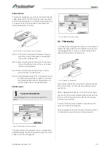
Step 2.1: If necessary, loosen the cutter head guard
(Pos. H, Fig. 10) to permit the fence assembly
to move freely without being constrained by
the guard.
Step 2.2: Loosen two fence assembly locking handles
(Pos. E, Fig. 10).
Step 2.3: Move the entire fence assembly to the desired
position; then re-tighten the handles (Pos. E,
Fig. 10).
Step 2.4: Readjust and secure the cutter head guard.
Tilt the fence backward.
Step 2.5: The fence (Pos. A, Fig. 10) can be tilted back-
ward (Pos. D, Fig. 10) up to 45°(that is, for a to-
tal included angle of 135° from table surface)
as follows:
a) Loosen locking handles (Pos. F, Fig. 10).
b) Tilt the fence back (Pos. A & Pos. C, Fig. 10)
to the desired angle up to 135 degrees.
c) Tighten the locking handles (Pos. F, Fig.10).
d) Readjust and secure the cutter head guard.
8.2 Adjustments
8.2.1 Table and knife adjustments
For accurate jointing, at least three things must be true:
- Infeed and outfeed tables must be coplanar.
- Knives or knife inserts must be set in the cutter head
so that the highest point of their arc is level with the
outfeed table.
- On the standard cutter head, knives must be paral-
lel with the outfeed table across the entire length of
the knives.
Fig. 11: Table setting
These alignments are explained below:
Coplanar Alignment
Definition of coplanar
When the infeed table is set to the same level as the out-
feed table and together both tables form a "perfect" flat
surface, the tables are said to be coplanar.
For optimum performance of the jointer, the infeed and
outfeed tables must be coplanar. If they are not, the fi-
nished workpiece may have a slight taper or twist
across jointed its width or length.
The tables have been set coplanar at the factory, but
they should be double-checked by the operator.
Also, as the machine undergoes use, the tables should
be checked occasionally and adjusted if necessary.
The procedure described below uses a steel straight
edge to set the tables, which should be accurate
enough for most purposes.
Important: The tables must be locked in position when
performing the following test:
Step 1: Disconnect the thicknesser from power source.
Step 2: Loosen the lock knob (Pos. A, Fig. 11) and slide
the cutter head guard (Pos. B & Pos. C) to clear
the table.
Step 3: Slide the fence assembly back (Pos. H & Pos. E,
Fig. 11) as far as it will go, or remove it from the
machine entirely.
Step 4: Rotate the cutter head to avoid knife interference.
Step 5: Place a straight edge (Pos. D, Fig. 11) across the
front of the outfeed table (Pos. F, Fig. 11) and ex-
tending over the infeed table (Pos. G, Fig. 11).
Note the position of the infeed table (Pos. G, Fig.
11). Note the position of the straight edge in Fi-
gure 9 with respect to the fence (Pos. H, Fig. 11).
Step 6: Raise the infeed table (Pos. G, Fig. 11) until it
contacts the straight edge (Pos. D, Fig. 11). The
straight edge should be straight and level over
both tables.
Tips and recomendations
You can use a reference piece or a measuring
instrument to facilitate the alignment of the stop.
ATTENTION!
The machine must be switched off at the ON/OFF
switch before switching from planer to thickness ope-
ration.
Содержание 5904026
Страница 36: ...36 ADH Series Version 1 02 Spare parts Spare parts drawing 2 Fig 27 Spare parts drawing 2 ADH 26 C ...
Страница 37: ...Spare parts ADH Series Version 1 02 37 Spare parts drawing 3 Fig 28 Spare parts drawing 3 ADH 26 C ...
Страница 38: ...38 ADH Series Version 1 02 Spare parts Spare parts drawing 4 Fig 29 Spare parts drawing 4 ADH 26 C ...
Страница 39: ...Spare parts ADH Series Version 1 02 39 Spare parts drawing 5 Fig 30 Spare parts drawing 5 ADH 26 C ...
Страница 40: ...40 ADH Series Version 1 02 Spare parts Spare parts drawing 6 Fig 31 Spare parts drawing 6 ADH 26 C ...
Страница 41: ...Spare parts ADH Series Version 1 02 41 Spare parts drawing 7 Fig 32 Spare parts drawing 7 ADH 26 C ...
Страница 43: ...Spare parts ADH Series Version 1 02 43 Spare parts drawing 2 Fig 34 Spare parts drawing 2 ADH 31 C ...
Страница 44: ...44 ADH Series Version 1 02 Spare parts Spare parts drawing 3 Fig 35 Spare parts drawing 3 ADH 31 C ...
Страница 45: ...Spare parts ADH Series Version 1 02 45 Spare parts drawing 4 Fig 36 Spare parts drawing 4 ADH 31 C ...
Страница 46: ...46 ADH Series Version 1 02 Spare parts Spare parts drawing 5 Fig 37 Spare parts drawing 5 ADH 31 C ...
Страница 47: ...Spare parts ADH Series Version 1 02 47 Spare parts drawing 6 Fig 38 Spare parts drawing 6 ADH 31 C ...
Страница 49: ...Spare parts ADH Series Version 1 02 49 Spare parts drawing 2 Fig 40 Spare parts drawing 2 ADH 41 C ...
Страница 50: ...50 ADH Series Version 1 02 Spare parts Spare parts drawing 3 Fig 41 Spare parts drawing 3 ADH 41 C ...
Страница 51: ...Spare parts ADH Series Version 1 02 51 Spare parts drawing 4 Fig 42 Spare parts drawing 4 ADH 41 C ...
Страница 52: ...52 ADH Series Version 1 02 Spare parts Spare parts drawing 5 Fig 43 Spare parts drawing 5 ADH 41 C ...
Страница 53: ...Spare parts ADH Series Version 1 02 53 Spare parts drawing 6 Fig 44 Spare parts drawing 6 ADH 41 C ...
Страница 54: ...54 ADH Series Version 1 02 Spare parts Spare parts drawing 7 Fig 45 Spare parts drawing 7 ADH 41 C ...
Страница 57: ...Notes ADH Series Version 1 02 57 15 Notes ...
Страница 58: ...www holzstar de ...


