20
ADH-Series | Version 1.02
Operation
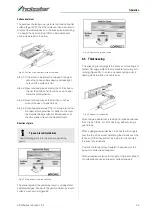
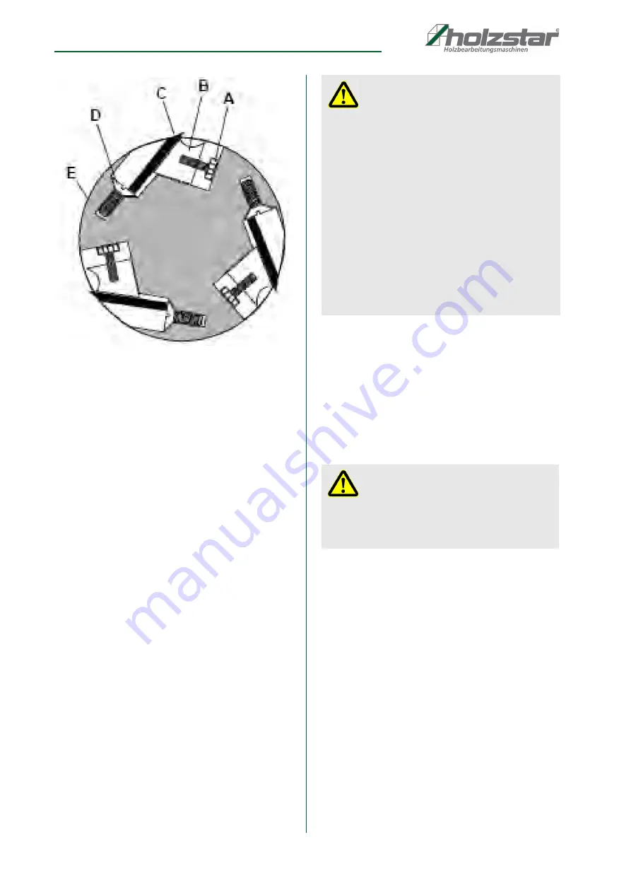
Fig. 15: Cutter head cross-section
Step 6: Note the position of the knife blade with respect
to the straight edge, then move the straight
edge to the other side of the table and again
note the position of the knife blade with respect
to the straight edge. Blade number one must be
at the same height at each end and must also
be at the same height as the outfeed table (bot-
tom of straight edge). If this is not the case, ad-
justment is required as follows:
Step 6.1: Slightly loosen five gib lock screws (Pos. A,
Fig. 14) by turning into the lock bar (Pos. B,
Fig. 14), clockwise as viewed from the infeed
table (Pos. G, Fig. 14).
Step 7: Adjust the knife height by turning jack screws
(Pos. D, Fig. 14) upon which the knives rest. To
lower the knife, turn the screw clockwise. To
raise, turn the screw counterclockwise.
Step 8: When the knife is at the proper height, alterna-
tely tighten the five gib lock screws (Pos. A,
Fig. 14).
Step 9: Repeat steps 4 – 8 for knives two and three.
D
8.2.3 Replacement of cutting knives
Disconnect machine from power source before making
any adjustments. Failure to comply may cause serious
injury.
Step 1: Disconnect machine from the power source.
Step 2: Remove the cutter head guard (Pos. B, Fig. 9).
Step 3: Turn all five screws (Pos. A, Fig. 14 and Fig. 15)
into the lock bar (Pos. B, Fig. 14 and Fig. 15) by
turning in a clockwise direction as viewed from
the infeed table (Pos. G, Fig. 14 and Fig. 15).
Step 4: Carefully remove the cutter knife (Pos. C, Fig. 14
and Fig. 15) and lock bar (Pos. B, Fig. 14 and
Fig. 15).
Step 5: Repeat for remaining two knives.
Step 6: Thoroughly clean all surfaces of the cutter head,
knife slots and lock bars of any dust or debris.
Step 7: Insert replacement knife (Pos. C, Fig. 15) into the
knife slot, making sure it faces the proper direction.
Step 8: Insert lock bar (Pos. B, Fig. 15) and tighten just
enough to hold in place.
Step 9: Repeat steps for other two knives.
ATTENTION!
- For workpieces with different thicknesses, first ma-
chine the stronger side (risk of wedging).
- Divide greater material removal into individual in-
feed steps.
- If wedging occurs, reduce infeed.
- Clean the worktable regularly.
- Make sure that the workpieces are free of resin or
dirt.
- Do not treat the worktable with lubricating oil or
grease.
- Use roller supports or extensions for long work-
pieces.
- Always machine workpieces to their full length.
- Do not machine bent or deformed workpieces.
DANGER!
Cutter head knives are dangerously sharp! Use
extreme caution when inspecting, removing, shar-
pening or replacing knives into the cutter head. Fai-
lure to comply may cause serious injury
Содержание 5904026
Страница 36: ...36 ADH Series Version 1 02 Spare parts Spare parts drawing 2 Fig 27 Spare parts drawing 2 ADH 26 C ...
Страница 37: ...Spare parts ADH Series Version 1 02 37 Spare parts drawing 3 Fig 28 Spare parts drawing 3 ADH 26 C ...
Страница 38: ...38 ADH Series Version 1 02 Spare parts Spare parts drawing 4 Fig 29 Spare parts drawing 4 ADH 26 C ...
Страница 39: ...Spare parts ADH Series Version 1 02 39 Spare parts drawing 5 Fig 30 Spare parts drawing 5 ADH 26 C ...
Страница 40: ...40 ADH Series Version 1 02 Spare parts Spare parts drawing 6 Fig 31 Spare parts drawing 6 ADH 26 C ...
Страница 41: ...Spare parts ADH Series Version 1 02 41 Spare parts drawing 7 Fig 32 Spare parts drawing 7 ADH 26 C ...
Страница 43: ...Spare parts ADH Series Version 1 02 43 Spare parts drawing 2 Fig 34 Spare parts drawing 2 ADH 31 C ...
Страница 44: ...44 ADH Series Version 1 02 Spare parts Spare parts drawing 3 Fig 35 Spare parts drawing 3 ADH 31 C ...
Страница 45: ...Spare parts ADH Series Version 1 02 45 Spare parts drawing 4 Fig 36 Spare parts drawing 4 ADH 31 C ...
Страница 46: ...46 ADH Series Version 1 02 Spare parts Spare parts drawing 5 Fig 37 Spare parts drawing 5 ADH 31 C ...
Страница 47: ...Spare parts ADH Series Version 1 02 47 Spare parts drawing 6 Fig 38 Spare parts drawing 6 ADH 31 C ...
Страница 49: ...Spare parts ADH Series Version 1 02 49 Spare parts drawing 2 Fig 40 Spare parts drawing 2 ADH 41 C ...
Страница 50: ...50 ADH Series Version 1 02 Spare parts Spare parts drawing 3 Fig 41 Spare parts drawing 3 ADH 41 C ...
Страница 51: ...Spare parts ADH Series Version 1 02 51 Spare parts drawing 4 Fig 42 Spare parts drawing 4 ADH 41 C ...
Страница 52: ...52 ADH Series Version 1 02 Spare parts Spare parts drawing 5 Fig 43 Spare parts drawing 5 ADH 41 C ...
Страница 53: ...Spare parts ADH Series Version 1 02 53 Spare parts drawing 6 Fig 44 Spare parts drawing 6 ADH 41 C ...
Страница 54: ...54 ADH Series Version 1 02 Spare parts Spare parts drawing 7 Fig 45 Spare parts drawing 7 ADH 41 C ...
Страница 57: ...Notes ADH Series Version 1 02 57 15 Notes ...
Страница 58: ...www holzstar de ...


