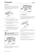
Operation
ADH-Series | Version 1.02
15
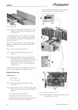
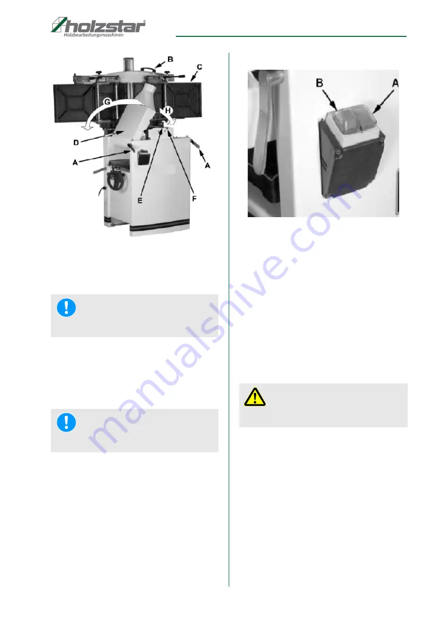
Fig. 6: Conversion to thickness function
Step 3: Position the dust chute (D, H Fig. 6) to the right.
Use extreme care to avoid contact with cutter head
knives.
8.1.2 Conversion from thickness to planer function
Step 1: Pull the release knob (Pos. F, Fig. 6) and reposi-
tion the dust chute (Pos. D & Pos. G, Fig. 6) to the
left. It should be positioned as shown in Fig. 5,
Pos. D).
Step 2: Release the latch (Pos. E, Fig. 6) and bring the ta-
ble forward using the tilt handle (Pos. B, Fig. 6). It
should be positioned as shown in Fig. 2, Pos. C.
Step 3: Lock the table (Pos. C, Fig. 6) by pushing the lock
handles (Pos. A, Fig. 6) in toward the machine
and rotating down (away from the operator).
Power connection
Step 1: Plug the power cord into the wall outlet when a
properly sized plug is connected.
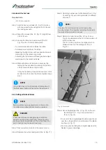
Step 2: Press the green on button (Pos. A, Fig. 7).
Step 3: Press the red off button (Pos. B, Fig. 4) to stop.
Fig. 7: START and STOP Buttons
A START button
B STOP button
8.1.3 Controls and Adjustments of the planer
Power feed
Placing the planer power feed handle (Pos. D, Fig. 8) in
the up position turns the planer power feed on (see ar-
row). Placing the handle in the down position turns the
power feed off.
Table lock
Turn the table lock (Pos. E, Fig. 8) clockwise to lock the
height adjustment handwheel (Pos. F, Fig. 8) and secure
the planer table (Pos. C, Fig. 8) in its selected position.
Turn the table lock (Pos. E, Fig. 8) counterclockwise to
release and permit table adjustment.
Table height adjustment
Step 1: Unlock the table lock (E).
Step 2: Rotate the height adjustment handwheel (Pos. F,
Fig. 8) clockwise to raise the planer table (Pos.
C, Fig. 8), counterclockwise to lower.
Step 3: Lock the table lock (Pos. E, Fig. 8). Each revolu-
tion of the handwheel (Pos. F, Fig. 8) results in a
4mm up or down movement of the table (Pos. C,
Fig. 8).
A scale on the handwheel column indicates the amount
of handwheel rotation. A pointer (Pos. B, Fig. 8) indica-
NOTE!
The planer table may need to be lowered to allow
clearance needed to position the dust collector.
NOTE!
Table is heavy. Use care when lowering. Failure to
comply may cause serious injury.
ATTENTION!
After completing the adjustment work, tighten all loc-
king elements again.
Содержание 5904026
Страница 36: ...36 ADH Series Version 1 02 Spare parts Spare parts drawing 2 Fig 27 Spare parts drawing 2 ADH 26 C ...
Страница 37: ...Spare parts ADH Series Version 1 02 37 Spare parts drawing 3 Fig 28 Spare parts drawing 3 ADH 26 C ...
Страница 38: ...38 ADH Series Version 1 02 Spare parts Spare parts drawing 4 Fig 29 Spare parts drawing 4 ADH 26 C ...
Страница 39: ...Spare parts ADH Series Version 1 02 39 Spare parts drawing 5 Fig 30 Spare parts drawing 5 ADH 26 C ...
Страница 40: ...40 ADH Series Version 1 02 Spare parts Spare parts drawing 6 Fig 31 Spare parts drawing 6 ADH 26 C ...
Страница 41: ...Spare parts ADH Series Version 1 02 41 Spare parts drawing 7 Fig 32 Spare parts drawing 7 ADH 26 C ...
Страница 43: ...Spare parts ADH Series Version 1 02 43 Spare parts drawing 2 Fig 34 Spare parts drawing 2 ADH 31 C ...
Страница 44: ...44 ADH Series Version 1 02 Spare parts Spare parts drawing 3 Fig 35 Spare parts drawing 3 ADH 31 C ...
Страница 45: ...Spare parts ADH Series Version 1 02 45 Spare parts drawing 4 Fig 36 Spare parts drawing 4 ADH 31 C ...
Страница 46: ...46 ADH Series Version 1 02 Spare parts Spare parts drawing 5 Fig 37 Spare parts drawing 5 ADH 31 C ...
Страница 47: ...Spare parts ADH Series Version 1 02 47 Spare parts drawing 6 Fig 38 Spare parts drawing 6 ADH 31 C ...
Страница 49: ...Spare parts ADH Series Version 1 02 49 Spare parts drawing 2 Fig 40 Spare parts drawing 2 ADH 41 C ...
Страница 50: ...50 ADH Series Version 1 02 Spare parts Spare parts drawing 3 Fig 41 Spare parts drawing 3 ADH 41 C ...
Страница 51: ...Spare parts ADH Series Version 1 02 51 Spare parts drawing 4 Fig 42 Spare parts drawing 4 ADH 41 C ...
Страница 52: ...52 ADH Series Version 1 02 Spare parts Spare parts drawing 5 Fig 43 Spare parts drawing 5 ADH 41 C ...
Страница 53: ...Spare parts ADH Series Version 1 02 53 Spare parts drawing 6 Fig 44 Spare parts drawing 6 ADH 41 C ...
Страница 54: ...54 ADH Series Version 1 02 Spare parts Spare parts drawing 7 Fig 45 Spare parts drawing 7 ADH 41 C ...
Страница 57: ...Notes ADH Series Version 1 02 57 15 Notes ...
Страница 58: ...www holzstar de ...


