Operation
ADH-Series | Version 1.02
19
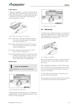
Adjustment of the front area:
Required tools:
- 2 x 13 mm. wrench
Step 1: Hold the hex cap screws (A1, Fig. 13) in place
with one wrench while using the other to loosen
the locking hex nuts.
Step 2: Adjust the screws (Pos. A1, Fig. 13) slightly from
1/8 to 1/4 turn.
Step 3: Loosen the three hex head screws (Pos. B1,
Fig. 13) with a 13 mm socket wrench:
- A counterclockwise turn willraise the table;
- A clockwise turn will lower the table.
- Adjusting the right screw will have greatest adjust-
ment impact to the table's right side;
- Adjusting the left screws will have greatest adjust-
ment impact to the table's left side.
Step 4: When adjustment is complete, secure by tigh-
tening the hex nut while maintaining the position
of the screw with the second wrench.
It may be necessary to repeat the exercise in this
section more than once to achieve coplanar align-
ment.
8.2.2 Setting cutter head knives
Step 1: Disconnect machine from the power source.
Step 2: Remove the cutter head guard (Pos. B, Fig. 11).
Step 3: Carefully number each knife blade (Pos. C, Fig.
14 and Fig. 15) with a magic marker to differen-
tiate each.
Step 4: Rotate the cutter head (Pos. E, Fig. 14 and
Fig. 15) and determine the 12 o'clock position of
knife number one.
The 12 o'clock position is the highest point a
blade will reach in the cutting arc (Pos. C,
Fig. 15).
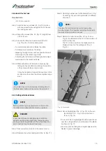
Fig. 14: Cutter head
Step 5: Set a straightedge (Pos. J, Fig. 14) on the out-
feed table (Pos. F, Fig. 14) near the fence
(Pos. H, Fig. 14).
- One end of the straightedge should be positioned
over the cutting knife (C) near the end of the blade
as shown in Fig. 12.
- Use care when handling the straight edge near the
blades to prevent damage.
NOTE!
If the table does not lock properly after adjustment,
the thicknesser table lock lever must be adjusted.
NOTE!
Before performing any adjustments in this section,
the infeed and outfeed tables must be coplanar.
DANGER!
Cutter head knives are dangerously sharp! Use
extreme caution when inspecting, removing, shar-
pening or replacing knives into the cutter head. Fai-
lure to comply may cause serious injury
NOTE!
To rotate the cutter head the cutter head pulley
must be turned. This requires removing the panel on
the back of the cabinet for access.
Содержание 5904026
Страница 36: ...36 ADH Series Version 1 02 Spare parts Spare parts drawing 2 Fig 27 Spare parts drawing 2 ADH 26 C ...
Страница 37: ...Spare parts ADH Series Version 1 02 37 Spare parts drawing 3 Fig 28 Spare parts drawing 3 ADH 26 C ...
Страница 38: ...38 ADH Series Version 1 02 Spare parts Spare parts drawing 4 Fig 29 Spare parts drawing 4 ADH 26 C ...
Страница 39: ...Spare parts ADH Series Version 1 02 39 Spare parts drawing 5 Fig 30 Spare parts drawing 5 ADH 26 C ...
Страница 40: ...40 ADH Series Version 1 02 Spare parts Spare parts drawing 6 Fig 31 Spare parts drawing 6 ADH 26 C ...
Страница 41: ...Spare parts ADH Series Version 1 02 41 Spare parts drawing 7 Fig 32 Spare parts drawing 7 ADH 26 C ...
Страница 43: ...Spare parts ADH Series Version 1 02 43 Spare parts drawing 2 Fig 34 Spare parts drawing 2 ADH 31 C ...
Страница 44: ...44 ADH Series Version 1 02 Spare parts Spare parts drawing 3 Fig 35 Spare parts drawing 3 ADH 31 C ...
Страница 45: ...Spare parts ADH Series Version 1 02 45 Spare parts drawing 4 Fig 36 Spare parts drawing 4 ADH 31 C ...
Страница 46: ...46 ADH Series Version 1 02 Spare parts Spare parts drawing 5 Fig 37 Spare parts drawing 5 ADH 31 C ...
Страница 47: ...Spare parts ADH Series Version 1 02 47 Spare parts drawing 6 Fig 38 Spare parts drawing 6 ADH 31 C ...
Страница 49: ...Spare parts ADH Series Version 1 02 49 Spare parts drawing 2 Fig 40 Spare parts drawing 2 ADH 41 C ...
Страница 50: ...50 ADH Series Version 1 02 Spare parts Spare parts drawing 3 Fig 41 Spare parts drawing 3 ADH 41 C ...
Страница 51: ...Spare parts ADH Series Version 1 02 51 Spare parts drawing 4 Fig 42 Spare parts drawing 4 ADH 41 C ...
Страница 52: ...52 ADH Series Version 1 02 Spare parts Spare parts drawing 5 Fig 43 Spare parts drawing 5 ADH 41 C ...
Страница 53: ...Spare parts ADH Series Version 1 02 53 Spare parts drawing 6 Fig 44 Spare parts drawing 6 ADH 41 C ...
Страница 54: ...54 ADH Series Version 1 02 Spare parts Spare parts drawing 7 Fig 45 Spare parts drawing 7 ADH 41 C ...
Страница 57: ...Notes ADH Series Version 1 02 57 15 Notes ...
Страница 58: ...www holzstar de ...


