Care, maintenance and repair
ADH-Series | Version 1.02
29
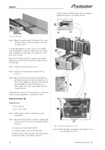
Fig. 25: Sharpening the knives
Step 4: Lay the stone on the infeed table.
Step 5: Lower the infeed table and turn the cutter head
by turning the cutter head pulley. The infeed ta-
ble height is set properly when the stone's sur-
face is flush with the knife bevel.
Step 6: Keep the cutter head from rotating by grasping
the cutter head pulley while sliding the stone
back and forth across the table.
Step 7: Take the same amount of passes for all three
blades.
When the blades have been sharpened and still are not
cutting efficiently, trying to touch up the blades further
will only cause the formation of a second beveled edge.
When this starts to happen, it is time to replace blades
with another set. It is recommended to keep a second
set of blades on hand so that they may be installed while
the first set is being professionally sharpened.
9.3 Care after work
Step 1: Disconnect the mains plug from the socket.
Step 2: Empty and clean the suction device.
Step 3: Clean the machine from chips and planing dust
with compressed air and/or with a dry cloth.
Step 4: Spray or oil all unpainted metal surfaces with a
little anti-rust spray.
Step 5: Oil the shaft and bearings.
Step 6: Check the machine for damage to the safety de-
vices and the planing knife. If necessary, carry
out or arrange for the repair to be carried out in
accordance with the safety instructions.
Step 7: Check the machine regularly:
- Appropriate tension of the drive belt.
- Loose bolts and nuts.
- Worn or damaged switches.
- Worn or damaged planing knives.
Step 8: Check the drive belt every 3 months, monthly if
used daily, replace if worn or damaged.
9.3.1 Functional testing
A functional test should be carried out before each use.
Step 1: The drive belt must be tensioned.
Step 2: The planing knife must rotate freely and must not
jam.
Step 3: Check the connecting cable for damage.
9.3.2 Suction
Check the suction system daily for sufficient function. If
the extraction system does not function or functions only
to a limited extent, it must be repaired. Only then may
planer-thicknesser be put into operation.
9.3.3 Lubrication
Use a good grade of light grease on the steel adjusting
screws located in the raising and lowering mechanisms
of the work tables.
The cutter head ball bearings are lifetime lubricated and
need no further care.
9.4 Maintenance and repair
Maintenance and repair work may only be carried out by
qualified personnel.
If the planner thicknesser does not function properly,
contact a specialist dealer or our customer service. The
contact details can be found in chapter 1.2 Customer
service.
All protective and safety devices must be reinstalled im-
mediately after completion of repair and maintenance
work.
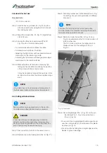
CAUTION!
Health hazard!
Wood dust and chips can damage the lungs when
inhaled.
Wear a dust mask when emptying the collection con-
tainer and when cleaning the exhaust system.
Use protective gloves!
Wear a dust mask!
NOTE!
Never use strong cleaning agents for any cleaning ta-
sks. This may damage or destroy the device.
Ausgabe-
tisch
Eingabetisch
Abziehstein teilweise mit
Papier umwickelt
Schneidkopf
Содержание 5904026
Страница 36: ...36 ADH Series Version 1 02 Spare parts Spare parts drawing 2 Fig 27 Spare parts drawing 2 ADH 26 C ...
Страница 37: ...Spare parts ADH Series Version 1 02 37 Spare parts drawing 3 Fig 28 Spare parts drawing 3 ADH 26 C ...
Страница 38: ...38 ADH Series Version 1 02 Spare parts Spare parts drawing 4 Fig 29 Spare parts drawing 4 ADH 26 C ...
Страница 39: ...Spare parts ADH Series Version 1 02 39 Spare parts drawing 5 Fig 30 Spare parts drawing 5 ADH 26 C ...
Страница 40: ...40 ADH Series Version 1 02 Spare parts Spare parts drawing 6 Fig 31 Spare parts drawing 6 ADH 26 C ...
Страница 41: ...Spare parts ADH Series Version 1 02 41 Spare parts drawing 7 Fig 32 Spare parts drawing 7 ADH 26 C ...
Страница 43: ...Spare parts ADH Series Version 1 02 43 Spare parts drawing 2 Fig 34 Spare parts drawing 2 ADH 31 C ...
Страница 44: ...44 ADH Series Version 1 02 Spare parts Spare parts drawing 3 Fig 35 Spare parts drawing 3 ADH 31 C ...
Страница 45: ...Spare parts ADH Series Version 1 02 45 Spare parts drawing 4 Fig 36 Spare parts drawing 4 ADH 31 C ...
Страница 46: ...46 ADH Series Version 1 02 Spare parts Spare parts drawing 5 Fig 37 Spare parts drawing 5 ADH 31 C ...
Страница 47: ...Spare parts ADH Series Version 1 02 47 Spare parts drawing 6 Fig 38 Spare parts drawing 6 ADH 31 C ...
Страница 49: ...Spare parts ADH Series Version 1 02 49 Spare parts drawing 2 Fig 40 Spare parts drawing 2 ADH 41 C ...
Страница 50: ...50 ADH Series Version 1 02 Spare parts Spare parts drawing 3 Fig 41 Spare parts drawing 3 ADH 41 C ...
Страница 51: ...Spare parts ADH Series Version 1 02 51 Spare parts drawing 4 Fig 42 Spare parts drawing 4 ADH 41 C ...
Страница 52: ...52 ADH Series Version 1 02 Spare parts Spare parts drawing 5 Fig 43 Spare parts drawing 5 ADH 41 C ...
Страница 53: ...Spare parts ADH Series Version 1 02 53 Spare parts drawing 6 Fig 44 Spare parts drawing 6 ADH 41 C ...
Страница 54: ...54 ADH Series Version 1 02 Spare parts Spare parts drawing 7 Fig 45 Spare parts drawing 7 ADH 41 C ...
Страница 57: ...Notes ADH Series Version 1 02 57 15 Notes ...
Страница 58: ...www holzstar de ...


