26
ADH-Series | Version 1.02
Operation
To edge:
Step 1: Make sure the fence is set to 90°. Double check
it with a square.
Step 2: Inspect stock for soundness and grain direction
(see „Direction of grain“).
Step 3: If the board is bowed (curved), place the con-
cave edge down on the infeed table.
Step 4: Set the infeed table for a cut of approximately
1.5mm.
Step 5: Hold the stock firmly against the fence and ta-
ble, feed the stock slowly and evenly over the
cutter head.
8.7 Beveling
Beveling an edge is the same operation as edge thick-
nessing, except that the fence is tilted to a specified
angle.
Make certain material being beveled is over 12 inches
long, more than 1/4 inch thick and 1 inch wide.
Beveling process:
Step 1: Use a bevel gauge to determine the desired
angle. Then set the fence to the same angle.
Step 2: Inspect stock for soundness and grain direction
(see „Direction of grain“).
Step 3: Set the infeed table for a cut of approximately
1.5 mm.
Step 4: If the board is bowed (curved), place the con-
cave edge down on the infeed table.
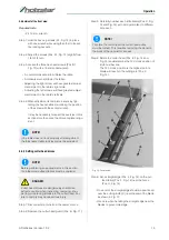
Step 5: Feed the stock through the cutter head, making
sure the face of the stock is completely flat
against the fence and the edge is making solid
contact on the infeed and outfeed tables
(Figure 24).
Fig. 24: Beveling process:
For wood wider than 3 inches – hold with fingers close
together near the top of the stock, lapping over the
board and extending over the fence. For wood less than
3 inches wide – use beveled push blocks and apply
pressure toward the fence. Keep fingers near top of
push block.
Several passes may be required to achieve the full be-
vel will probably take several passes.
8.8 Planer operations
Depth of cut
Thickness planing refers to the sizing of lumber to a de-
sired thickness while creating a level surface parallel to
the opposite side of the board. Board thickness that the
planer will produce is indicated by the scale and the
depthof- cut gauge . Preset the planer to the desired
thickness of the finished workpiece using the gauge.
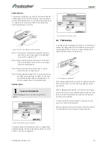
The depth-of-cut is adjusted by raising or lowering the
planer table (Pos. C, Fig. 8) using the handwheel
(Pos. F, Fig. 8).
The quality of thickness planning depends on the ope-
rator's judgment about the depth of cut.
The depth of cut depends on the width, hardness,
dampness, grain direction and grain structure of the
wood.
The maximum thickness of wood that can be removed
in one pass is 1/8” for planning operations on work-
pieces up to 5-1/2” wide.
The workpiece must be positioned away from the center
tab on the rollercase to cut 1/8”.
The maximum thickness of wood that can be removed
in one pass is 1/16” for planning operations on work-
pieces from 5-1/2” up to 12" wide.
For optimum planning performance, the depth of cut
should be less than 1/16”.
The board should be planed with shallow cuts until the
work has a level side. Once a level surface has been
created, flip the lumber and create parallel sides.
-
Holzblock
Anschlag
Ausgabetisch
Eingabetisch
ATTENTION!
The workpiece should be dressed before machining
on the planer-thicknesser.
ATTENTION!
In the case of workpieces with different thickness at
both ends, first add the end with the greater thick-
ness in order to avoid wedging.
Содержание 5904026
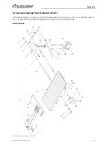
Страница 36: ...36 ADH Series Version 1 02 Spare parts Spare parts drawing 2 Fig 27 Spare parts drawing 2 ADH 26 C ...
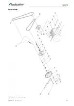
Страница 37: ...Spare parts ADH Series Version 1 02 37 Spare parts drawing 3 Fig 28 Spare parts drawing 3 ADH 26 C ...
Страница 38: ...38 ADH Series Version 1 02 Spare parts Spare parts drawing 4 Fig 29 Spare parts drawing 4 ADH 26 C ...
Страница 39: ...Spare parts ADH Series Version 1 02 39 Spare parts drawing 5 Fig 30 Spare parts drawing 5 ADH 26 C ...
Страница 40: ...40 ADH Series Version 1 02 Spare parts Spare parts drawing 6 Fig 31 Spare parts drawing 6 ADH 26 C ...
Страница 41: ...Spare parts ADH Series Version 1 02 41 Spare parts drawing 7 Fig 32 Spare parts drawing 7 ADH 26 C ...
Страница 43: ...Spare parts ADH Series Version 1 02 43 Spare parts drawing 2 Fig 34 Spare parts drawing 2 ADH 31 C ...
Страница 44: ...44 ADH Series Version 1 02 Spare parts Spare parts drawing 3 Fig 35 Spare parts drawing 3 ADH 31 C ...
Страница 45: ...Spare parts ADH Series Version 1 02 45 Spare parts drawing 4 Fig 36 Spare parts drawing 4 ADH 31 C ...
Страница 46: ...46 ADH Series Version 1 02 Spare parts Spare parts drawing 5 Fig 37 Spare parts drawing 5 ADH 31 C ...
Страница 47: ...Spare parts ADH Series Version 1 02 47 Spare parts drawing 6 Fig 38 Spare parts drawing 6 ADH 31 C ...
Страница 49: ...Spare parts ADH Series Version 1 02 49 Spare parts drawing 2 Fig 40 Spare parts drawing 2 ADH 41 C ...
Страница 50: ...50 ADH Series Version 1 02 Spare parts Spare parts drawing 3 Fig 41 Spare parts drawing 3 ADH 41 C ...
Страница 51: ...Spare parts ADH Series Version 1 02 51 Spare parts drawing 4 Fig 42 Spare parts drawing 4 ADH 41 C ...
Страница 52: ...52 ADH Series Version 1 02 Spare parts Spare parts drawing 5 Fig 43 Spare parts drawing 5 ADH 41 C ...
Страница 53: ...Spare parts ADH Series Version 1 02 53 Spare parts drawing 6 Fig 44 Spare parts drawing 6 ADH 41 C ...
Страница 54: ...54 ADH Series Version 1 02 Spare parts Spare parts drawing 7 Fig 45 Spare parts drawing 7 ADH 41 C ...
Страница 57: ...Notes ADH Series Version 1 02 57 15 Notes ...
Страница 58: ...www holzstar de ...

