22
ADH-Series | Version 1.02
Operation
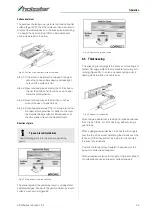
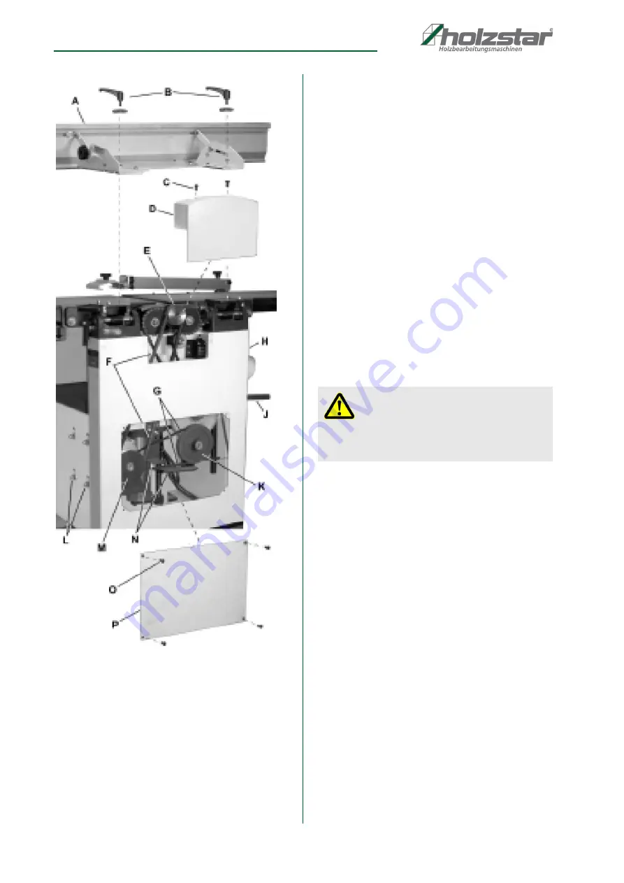
Fig. 16: Belt replacement
Concluding Steps
Step 11: Replace the cutter head drive belt (Pos. F, Fig.
16) by looping it around the cutter head pulley
(Pos. E, Fig. 16), then the larger (outside) motor
pulley (Pos. M, Fig. 16).
Step 12: Slide the motor so the mounting screws (Pos. L,
Fig. 16) rest back in the vertical slot openings,
then tighten the mounting screws.
Step 13: Replace the lower back panel (Pos. P, Fig. 16)
and secure with four button head socket
screws (Pos. O, Fig. 16).
Step 14: Replace the upper back panel (Pos. D, Fig. 16)
and secure with two button head socket screws
(Pos. C, Fig. 16).
Step 14: Replace the jointer fence assembly (Pos. A,
Fig. 16) and secure with two lock handle as-
semblies (Pos. B, Fig. 16).
8.2.5 Adjustment of the planer table
Checking planer table parallel to cutter head
The planer table is set parallel to the cutter head at the
factory and no further adjustment should be needed. If
your machine is planing a taper, first check to see if the
knives are properly adjusted in the cutter head (see
„Setting cutter head knives“) and make adjustments if
necessary.
After the knives are confirmed to be properly set, check
to see if the work table is set parallel to the cutter head
as follows.
Step 1: Disconnect machine from power source.
Step 2: Rotate the cutter head such that one of the knife
blades (Pos. A, Fig. 17) is at the 6 o'clock posi-
tion.
Step 3: Place a gauge block (Pos. B, Fig. 18) or another
measuring device on the work table (Pos. C,
Fig. 18) at one edge (Pos. D, Fig. 18) directly un-
der the cutter head.
DANGER!
Disconnect machine from power source before
making any adjustments.
Failure to comply may cause serious injury.
Содержание 5904026
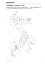
Страница 36: ...36 ADH Series Version 1 02 Spare parts Spare parts drawing 2 Fig 27 Spare parts drawing 2 ADH 26 C ...
Страница 37: ...Spare parts ADH Series Version 1 02 37 Spare parts drawing 3 Fig 28 Spare parts drawing 3 ADH 26 C ...
Страница 38: ...38 ADH Series Version 1 02 Spare parts Spare parts drawing 4 Fig 29 Spare parts drawing 4 ADH 26 C ...
Страница 39: ...Spare parts ADH Series Version 1 02 39 Spare parts drawing 5 Fig 30 Spare parts drawing 5 ADH 26 C ...
Страница 40: ...40 ADH Series Version 1 02 Spare parts Spare parts drawing 6 Fig 31 Spare parts drawing 6 ADH 26 C ...
Страница 41: ...Spare parts ADH Series Version 1 02 41 Spare parts drawing 7 Fig 32 Spare parts drawing 7 ADH 26 C ...
Страница 43: ...Spare parts ADH Series Version 1 02 43 Spare parts drawing 2 Fig 34 Spare parts drawing 2 ADH 31 C ...
Страница 44: ...44 ADH Series Version 1 02 Spare parts Spare parts drawing 3 Fig 35 Spare parts drawing 3 ADH 31 C ...
Страница 45: ...Spare parts ADH Series Version 1 02 45 Spare parts drawing 4 Fig 36 Spare parts drawing 4 ADH 31 C ...
Страница 46: ...46 ADH Series Version 1 02 Spare parts Spare parts drawing 5 Fig 37 Spare parts drawing 5 ADH 31 C ...
Страница 47: ...Spare parts ADH Series Version 1 02 47 Spare parts drawing 6 Fig 38 Spare parts drawing 6 ADH 31 C ...
Страница 49: ...Spare parts ADH Series Version 1 02 49 Spare parts drawing 2 Fig 40 Spare parts drawing 2 ADH 41 C ...
Страница 50: ...50 ADH Series Version 1 02 Spare parts Spare parts drawing 3 Fig 41 Spare parts drawing 3 ADH 41 C ...
Страница 51: ...Spare parts ADH Series Version 1 02 51 Spare parts drawing 4 Fig 42 Spare parts drawing 4 ADH 41 C ...
Страница 52: ...52 ADH Series Version 1 02 Spare parts Spare parts drawing 5 Fig 43 Spare parts drawing 5 ADH 41 C ...
Страница 53: ...Spare parts ADH Series Version 1 02 53 Spare parts drawing 6 Fig 44 Spare parts drawing 6 ADH 41 C ...
Страница 54: ...54 ADH Series Version 1 02 Spare parts Spare parts drawing 7 Fig 45 Spare parts drawing 7 ADH 41 C ...
Страница 57: ...Notes ADH Series Version 1 02 57 15 Notes ...
Страница 58: ...www holzstar de ...


