16
ADH-Series | Version 1.02
Operation
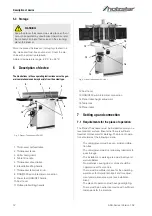
tes the table position relative to the cutter head on the
scale (A) located on the side of the cabinet.
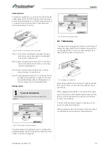
Fig. 8: Operating elements
8.1.4 Controls and Adjustments of the thicknesser
Outfeed Table Height Adjustment
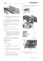
Lock knob (Pos. C, Fig. 9) and lifting handle (Pos. B, Fig.
9) control the height adjustment of the outfeed table
(Pos. A, Fig. 9).The outfeed table is initially adjusted at
the factory and should not be repositioned except du-
ring certain adjustments.
Infeed Table Height Adjustment
Lock knob (Pos. D, Fig. 9) and lifting handle (Pos. E, Fig.
9) control the height adjustment of the infeed table (Pos.
F, Fig. 9).To adjust:
Step 1: Loosen lock knob (Pos. D, Fig. 9).
Step 2: Raise the lifting handle (E) to raise the infeed ta-
ble for a shallow depth of cut. Lower the handle
for a deeper cut.
Step 3: Tighten the lock knob (Pos. D, Fig. 9).
Fig. 9: Thicknesser
Cutter head guard
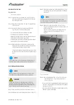
Properly positioned, the cutter head guard (Pos. H, Fig.
10) should rest against the fence (Pos. A, Fig. 10).
Fence movement
The fence (Pos. A, Fig. 10) can be moved forward (Pos.
B, Fig. 10) or backward (Pos. C, Fig. 10) across the
width (Pos. W, Fig. 10) of the table. It also tilts up to 45
degrees backwards (Pos. D, Fig. 10).
Fig. 10: Thicknesser
Step 1: Loosen the lock knob (Pos. J, Fig. 10), slide the
guard into position, then tighten the lock knob.
Step 2: To slide fence forward or backward:
When edge jointing, the fence assembly should
nperiodically be moved to different positions to
distribute wear on the cutter head knives. This is
done as follows:
NOTE!
A depth of cut of 1.5mm or less is recommended.
Содержание 5904026
Страница 36: ...36 ADH Series Version 1 02 Spare parts Spare parts drawing 2 Fig 27 Spare parts drawing 2 ADH 26 C ...
Страница 37: ...Spare parts ADH Series Version 1 02 37 Spare parts drawing 3 Fig 28 Spare parts drawing 3 ADH 26 C ...
Страница 38: ...38 ADH Series Version 1 02 Spare parts Spare parts drawing 4 Fig 29 Spare parts drawing 4 ADH 26 C ...
Страница 39: ...Spare parts ADH Series Version 1 02 39 Spare parts drawing 5 Fig 30 Spare parts drawing 5 ADH 26 C ...
Страница 40: ...40 ADH Series Version 1 02 Spare parts Spare parts drawing 6 Fig 31 Spare parts drawing 6 ADH 26 C ...
Страница 41: ...Spare parts ADH Series Version 1 02 41 Spare parts drawing 7 Fig 32 Spare parts drawing 7 ADH 26 C ...
Страница 43: ...Spare parts ADH Series Version 1 02 43 Spare parts drawing 2 Fig 34 Spare parts drawing 2 ADH 31 C ...
Страница 44: ...44 ADH Series Version 1 02 Spare parts Spare parts drawing 3 Fig 35 Spare parts drawing 3 ADH 31 C ...
Страница 45: ...Spare parts ADH Series Version 1 02 45 Spare parts drawing 4 Fig 36 Spare parts drawing 4 ADH 31 C ...
Страница 46: ...46 ADH Series Version 1 02 Spare parts Spare parts drawing 5 Fig 37 Spare parts drawing 5 ADH 31 C ...
Страница 47: ...Spare parts ADH Series Version 1 02 47 Spare parts drawing 6 Fig 38 Spare parts drawing 6 ADH 31 C ...
Страница 49: ...Spare parts ADH Series Version 1 02 49 Spare parts drawing 2 Fig 40 Spare parts drawing 2 ADH 41 C ...
Страница 50: ...50 ADH Series Version 1 02 Spare parts Spare parts drawing 3 Fig 41 Spare parts drawing 3 ADH 41 C ...
Страница 51: ...Spare parts ADH Series Version 1 02 51 Spare parts drawing 4 Fig 42 Spare parts drawing 4 ADH 41 C ...
Страница 52: ...52 ADH Series Version 1 02 Spare parts Spare parts drawing 5 Fig 43 Spare parts drawing 5 ADH 41 C ...
Страница 53: ...Spare parts ADH Series Version 1 02 53 Spare parts drawing 6 Fig 44 Spare parts drawing 6 ADH 41 C ...
Страница 54: ...54 ADH Series Version 1 02 Spare parts Spare parts drawing 7 Fig 45 Spare parts drawing 7 ADH 41 C ...
Страница 57: ...Notes ADH Series Version 1 02 57 15 Notes ...
Страница 58: ...www holzstar de ...


