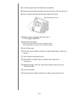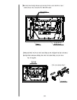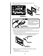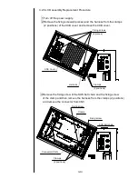
3-14
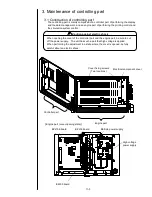
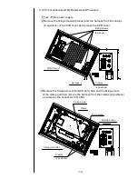
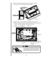
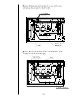
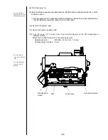
4 Remove the fixing screws (6 pieces) of the hinges(2 positions)
and then remove the controller part from the body.
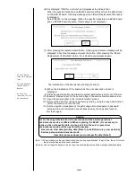
5Remove the 3 connectors (CN2
、
CN4
、
CN8) on EZJ124 board
and the touch panel connection cable. And then remove the fixing screws
(5 pieces) of EZJ124 board and remove EZJ124 board.
Caution
!
When inserting or removing the touch panel
connection cable into the connector on EZJ124
board, always hold both sides of reinforced section
for connection (as shown in the figure) so that the
cable is not bent.
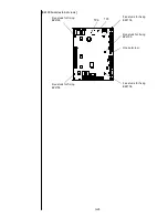
Fixing screws
(5 pieces)
Battery connection
cable(CN2)
EZJ124 board
EZJ97 board
Connector for
EZJ97 board
(CN4)
LCD
(Backside of panel)
Touch panel
connection cable
Battery
Connector for
LCD (CN8)
Fixing screws
(6 pieces)
Controller part
Hinges
(2 potions)
Содержание IJ PH
Страница 1: ...Service Manual HITACHI Printer Model PH Revision Aug 2011 Version First edition ...
Страница 2: ... Revision of PH service manual Revision Chapter Revised Page ...
Страница 13: ...1 2 2 Main body internal PH D 1 8 ...
Страница 80: ...3 25 3 25 Circuit diagram of EZJ95 ...
Страница 201: ...7 1 7 Attached Drawing 7 1 Circulation System Diagram ...
Страница 202: ...7 2 7 2 Electrical Connection Diagram ...
Страница 205: ...7 5 7 4 Dimensions around charge electrode and deflection electrode Nozzle diameter 65 um ...

