3-17
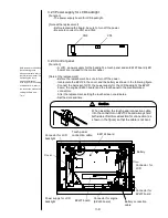
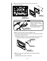
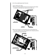
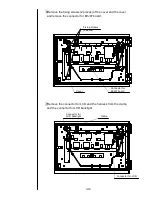
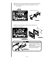
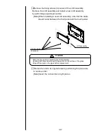
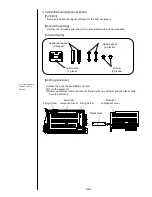
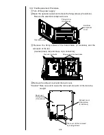
10Remove the fixing screws (4 pieces) of the LCD assembly.
Remove the LCD assembly and install a new LCD assembly
by performing opposite procedure.
[Note] When installing a new LCD assembly, note that the dusts
doesn't enter between the front panel and the touch panel.
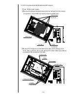
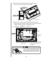
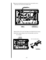
11 Return the unit to its original state by performing the procedure
in reverse order.
[Note] Insert the connectors to right places.
LCD assembly
Fixing screws
(4 pieces)
Wear the gloves when replacing the LCD assembly.
Handling with bare hands leaves fingerprints on the surface of the glass.
Wipe off the dust on the glass before replacement.
!
Caution
Содержание IJ PH
Страница 1: ...Service Manual HITACHI Printer Model PH Revision Aug 2011 Version First edition ...
Страница 2: ... Revision of PH service manual Revision Chapter Revised Page ...
Страница 13: ...1 2 2 Main body internal PH D 1 8 ...
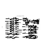
Страница 80: ...3 25 3 25 Circuit diagram of EZJ95 ...
Страница 201: ...7 1 7 Attached Drawing 7 1 Circulation System Diagram ...
Страница 202: ...7 2 7 2 Electrical Connection Diagram ...
Страница 205: ...7 5 7 4 Dimensions around charge electrode and deflection electrode Nozzle diameter 65 um ...

