


5-2
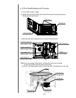
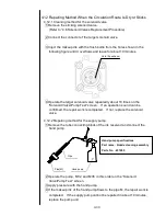
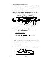
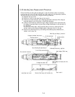
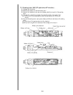
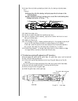
5.2 Nozzles Replacement Procedure
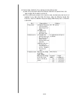
(appendix: nozzle drive conditions)
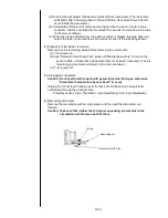
(1) Depressurize the printer.
(2) Unscrew the video signal wire setscrews and the charged electrode setscrews, and
remove the charged electrode.
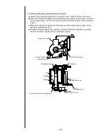
(3) Remove the nozzle setscrew (2 locations), the nozzle IN joint presser foot
(sealing valve side) and the excitation connector.
“Caution” A filter is put in the terminal area (inside the sealing valve) of the nozzle IN
joint and therefore, be careful about dropout.
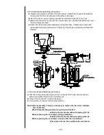
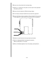
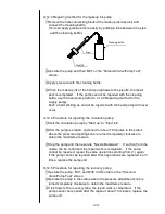
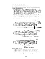
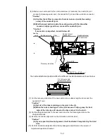
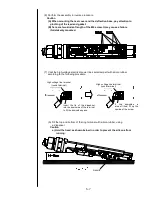
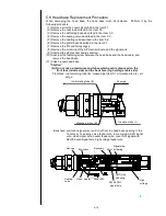
(4) Cut off the nozzle side of the nozzle OUT joint by a cutter or the like.
“Caution” When removing the nozzle OUT joint, remove it so as not to
pull the main body side tube.
"Caution"
(A) If you scratch the coupling with a cutter or the like, it may cause an ink
leakage and so on.
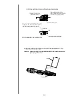
(B) When removing a cut piece of the tube, cut the tube piece and pull it
off the coupling.
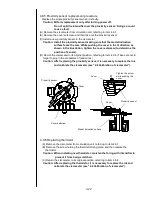
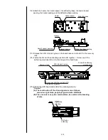
(5) Pull out the nozzle upward with a slope while taking up the front edge of the nozzle.
Sealing valve
Nozzle OUT
joint
Filter
Nozzle IN joint
presser foot
Nozzle setscrew
Excitation
connector
Video signal
wire setscrew
Charged
electrode
setscrew
Charged electrode
Nozzle OUT joint presser foot
Å
Main body side
Nozzle side
Æ
Cut off this part
Pull out the nozzle upward with a slope
Содержание IJ PH
Страница 1: ...Service Manual HITACHI Printer Model PH Revision Aug 2011 Version First edition ...
Страница 2: ... Revision of PH service manual Revision Chapter Revised Page ...
Страница 13: ...1 2 2 Main body internal PH D 1 8 ...
Страница 80: ...3 25 3 25 Circuit diagram of EZJ95 ...
Страница 201: ...7 1 7 Attached Drawing 7 1 Circulation System Diagram ...
Страница 202: ...7 2 7 2 Electrical Connection Diagram ...
Страница 205: ...7 5 7 4 Dimensions around charge electrode and deflection electrode Nozzle diameter 65 um ...


