


4-11
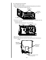
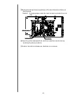
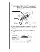
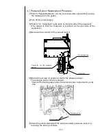
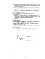
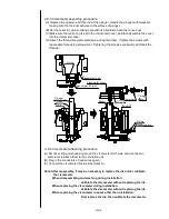
7 Remove the fixing screws (8 positions) at the upper and lower
connecting parts of the circulation unit. The pump unit can be removed.
"Caution 1": When removing the screws with a screwdriver, hold the
lower side of the unit door so that the unit door and hinge
may not be deformed.
"Caution 2": Put wiping paper under the pump unit to provide for an ink
drip.
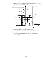
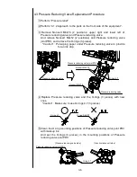
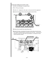
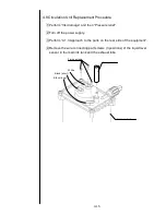
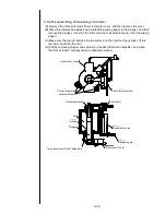
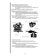
8 Clean the portion stained with ink and make sure that the O-rings (4
positions) are securely mounted in the concave parts of the lower-side
circulation unit. Then, install a pump unit by reversing the above
procedure.
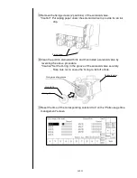
9 Perform “Ink refill” and adjust the pressure. Make sure that there is no
ink leak.
10 Reset the pump time to "0" on the “Parts usage time management”
screen.
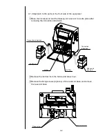
Insert the screwdriver
from this slit.
Fixing screw
(8 positions)
Unit door
Hold this portion.
*) This figure is for the
PXR-D. The main ink tank
is not attached for the
PXR-P.
Содержание IJ PH
Страница 1: ...Service Manual HITACHI Printer Model PH Revision Aug 2011 Version First edition ...
Страница 2: ... Revision of PH service manual Revision Chapter Revised Page ...
Страница 13: ...1 2 2 Main body internal PH D 1 8 ...
Страница 80: ...3 25 3 25 Circuit diagram of EZJ95 ...
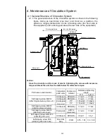
Страница 201: ...7 1 7 Attached Drawing 7 1 Circulation System Diagram ...
Страница 202: ...7 2 7 2 Electrical Connection Diagram ...
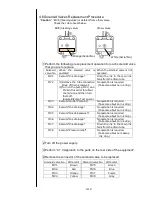
Страница 205: ...7 5 7 4 Dimensions around charge electrode and deflection electrode Nozzle diameter 65 um ...


