Section 4
♦
Operating the CMN-41
58
CMN-41 Series Installation and Operation Handbook
Copyright © 2009, Harris Corporation
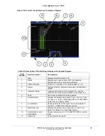
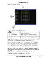
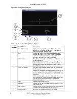
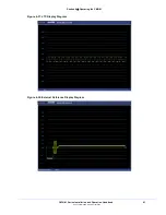
Figure 4-36. Timing Display Diagram
Table 4-15. Description of Timing Display Diagram
Field
Identifier
Field Information
Nomenclature
1
Selected reference
Displays the selected reference as REF: X where
X
is
ExtREF or LTC; the REF is selected in the Timing Setup
menu; also indicates reference format
2
Test
Indicates the input that is being measured against the
selected reference in Field Identifier 1; also displays the
input’s line rate/frame rate (shown in
Figure 4-36
as
525/59.94); selected in the Video Setup menu
3
VERT (Vertical )
The offset line in full-video lines between the reference and
the displayed video
Displays the Vertical Error Measurement as VERT: xxx
Line(s), where
xxx
is the measured difference between the
reference and the test input alignment of the vertical timing
(sync/TRS) in lines
4
HORZ (Horizontal)
The offset time in microseconds between the reference and
the displayed video.
Displays the Horizontal Error Measurement as HORZ: yy.yyy
μ
s, where
yy.yyy
is the measured difference between the
reference and the test input alignment of the horizontal timing
(sync/TRS)
Horizontal can be yellow at 0 µs. It displays the minimum
scale resolution at 1µ and the minimum timing resolution at
0.037 µs for HD (High Definition) and 0.74 µs for SD
(Standard Definition).
5
Input
Displays selected input (A or B)
6
Standard
Displays the line rate/frame rate; select the Standard in the
Video Setup menu
7
REF OFFSET
Displays that the zero point of the timing measurements are
offset from the REF selection by
xx
lines
yy.yyy
μ
s
8
Timing Graticule
Shows the timing graticules, cursors, and labels

