Section 4
♦
Operating the CMN-41
26
CMN-41 Series Installation and Operation Handbook
Copyright © 2009, Harris Corporation
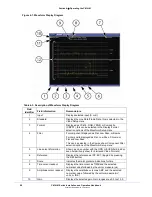
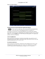
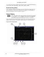
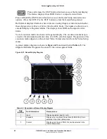
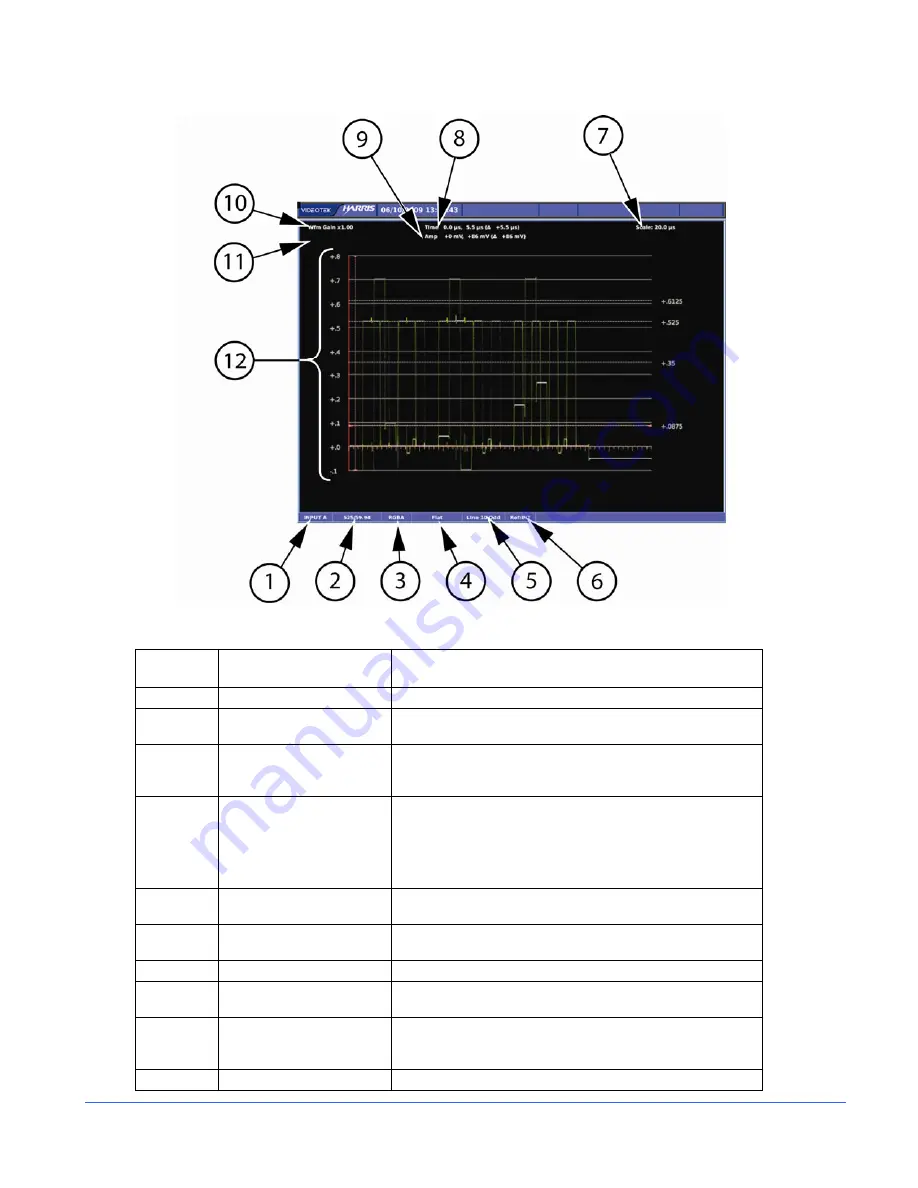
Figure 4-1. Waveform Display Diagram
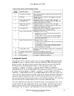
Table 4-3. Description of Waveform Display Diagram
Field
Identifier
Field information
Nomenclature
1
Input
Displays selected input (A or B)
2
Standard
Displays the Line Rate/Frame Rate; this is selected in the
Video Setup menu
3
Format
Displayed as YC
B
C
R
, RGB, YRGB, or Composite
(CMPST); this can be selected in the Display/Format
selection options of the Waveform Setup menu
4
Filter
For component displayed as Flat, Low Pass, or Bowtie
For composite displayed as Flat, Low Pass, Chroma, or
Flat and Low Pass
This can be selected in the Composite or Component Filter
selection options of the Waveform Setup menu
5
Line select information
Shown as Line number with the ODD or EVEN field (odd or
even field will only show for interlaced Video Formats)
6
Reference
Displays the reference as INT, EXT (toggled by pressing
the REF button)
7
Scale
Indicates the major graticule indications for time
8
Time cursor readout
Displays the time cursor as TIME and the selected
numerical value followed by the unit or measure (µs)
9
Amplitude cursor readout
Displays the amplitude cursor as AMP and the selected
numerical value, followed by the unit or measure (mV,
units, or IRE)
10
Gain
Displays the selected gain; Gain ranges are x0.5 to x15.0


