CE7000-UM-251-9370 7-33
7 DISASSEMBLY AND REASSEMBLY
CE7000-130/130AP/160
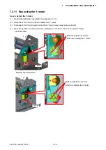
How to detach the X-motor
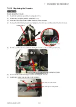
(1) Detach the right side cover (Refer to subsection 7.1.1.).
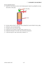
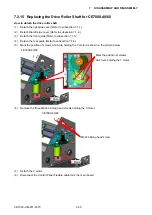
(2) Mark the position of screws which are holding the X motor as shown in the picture below.
Mark the position of screws which are holding the X motor.
(3) Remove the three M3L6 binding head screws holding the X-motor, then detach the X-motor from the
hole of right side plate.
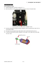
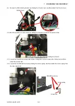
(4) Disconnect the X motor power relay cable and the X motor encoder cable from the X motor.
(5) Loosen the two M3L4WP set screws holding the X motor pulley, and then detach the X-motor pulley
from the X motor.
M3L4WP set screw
X motor pulley
X motor
Содержание CE7000-130
Страница 1: ...CE7000 UM 251 00 9370 CUTTING PLOTTER SERVICE MANUAL CE7000 40 60 130 160 130AP ...
Страница 2: ......
Страница 4: ...CE7000 UM 251 9370 II ...
Страница 72: ...CE7000 UM 251 9370 5 2 5 RECOMMENDED PARTS LIST ...
Страница 74: ......

