CE7000-UM-251-9370 8-51
8 Electrical Adjustment
8.17.2 Adjusting the Spacing Between Tool 1 and Tool 2
When the pen block was replaced or the 2nd Pen was removed, perform this adjustment.
Preparation
•
Prepare the two fiber tip-pens (KF700-BK) and the fiber tip-pen plunger (PHP31-FIBER).
Install the fiber tip-pens (KB700-BK) to the fiber tip-pen plunger (PHP31-FIBER) correctly, the length for tip
of fiber tip-pe is important to detect the pens.
How to adjust the spacing between tool 1 and tool 2
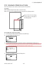
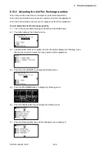
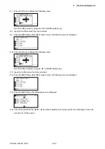
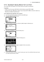
(1) Turn on the power while pressing the SLOW and the ENTER keys.
(2) The plotter displays the following menu.
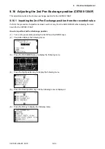
(3) Load the copy paper to the plotter, and then the plotter displays the following menu.
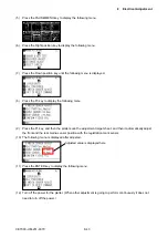
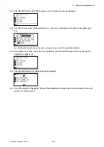
(4) Press the 3 key (SHEET) to display the following menu.
(5) Press the PAUSE/MENU key to display the following menu.
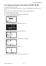
(6) Press the Right Position key to display the adjustment menu shown below.
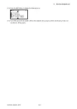
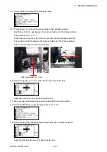
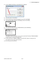
(7)
Install the fiber tip pens to the tool 1 holder (The fornt side is tool 1 for the CE7000-130AP.) and the 2nd
pen station (Right side plate of holder).
Содержание CE7000-130
Страница 1: ...CE7000 UM 251 00 9370 CUTTING PLOTTER SERVICE MANUAL CE7000 40 60 130 160 130AP ...
Страница 2: ......
Страница 4: ...CE7000 UM 251 9370 II ...
Страница 72: ...CE7000 UM 251 9370 5 2 5 RECOMMENDED PARTS LIST ...
Страница 74: ......

