CE7000-UM-251-9370 8-27
8 Electrical Adjustment
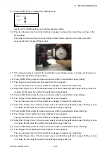
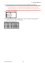
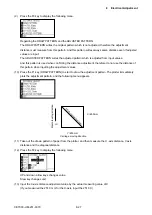
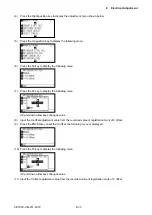
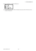
(9) Press the F3 key to display the following menu.
Regarding the DRAW PATTERN and the ADJUSTED PATTERN:
The DRAW PATTERN writes the original pattern which is not adjusted, therefore the adjustment
distance must measure from this pattern. And this pattern writes always same distance even if adjusted
values are input.
The ADJUSTED PATTERN writes the adjusted pattern which is adjusted from input values.
And this pattern is used when confirming the distance adjustment, therefore do not use the distance of
this pattern when inputting the adjustment values.
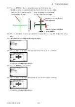
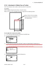
(10) Press the F1 key (DRAW PATTERN) to start to draw the adjustment pattern. The plotter immediately
plots the adjustment pattern, and the following menu appears.
+X
Y=250 mm
X=250 mm
Media feeding direction
Carriage moving direction
XY=Diagonal distance
(11) Take out the drawn pattern of paper from the plotter, and then measure the X -axis distance, Y-axis
distance and the diagonal distance.
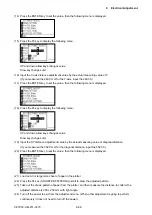
(12) Press the F2 key to display the following menu.
UP and down allow keys changes value
Slow key changes unit
(13) Input the X-axis distance adjustment value by the actual measuring value of X.
(If you measured the 251.0 mm for the X-axis, input the 251.00.)
Содержание CE7000-130
Страница 1: ...CE7000 UM 251 00 9370 CUTTING PLOTTER SERVICE MANUAL CE7000 40 60 130 160 130AP ...
Страница 2: ......
Страница 4: ...CE7000 UM 251 9370 II ...
Страница 72: ...CE7000 UM 251 9370 5 2 5 RECOMMENDED PARTS LIST ...
Страница 74: ......

