


CE7000-UM-251-9370 2-8
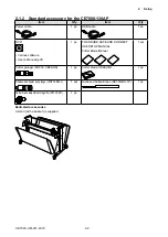
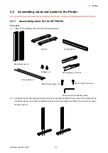
2 Setup
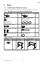
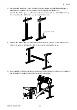
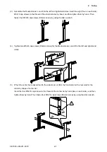
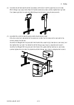
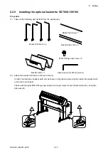
(6) Confirm the front side and the rear side for the stand by shape of center bar. Mount the plotter on
the stand by inserting the positioning pins on the stand into the positioning holes on the underside of
the plotter. Fasten with the four M5L20 cap screws (two longer screws for each side), using the Allen
wrench.
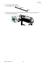
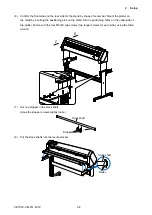
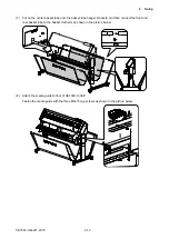
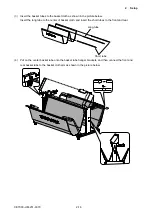
(7) Set one stopper in the stock shaft.
(Keep the stopper screws slightly loose.)
Stock shaft
Stopper
(8) Put the stock shafts into the media stocker.
Roller
Stock shaft
Содержание CE7000-130
Страница 1: ...CE7000 UM 251 00 9370 CUTTING PLOTTER SERVICE MANUAL CE7000 40 60 130 160 130AP ...
Страница 2: ......
Страница 4: ...CE7000 UM 251 9370 II ...
Страница 72: ...CE7000 UM 251 9370 5 2 5 RECOMMENDED PARTS LIST ...
Страница 74: ......


