


CE7000-UM-251-9370 7-18
7 DISASSEMBLY AND REASSEMBLY
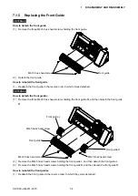
7.2.6 Replacing the Pen Block
How to detach the pen block
(1) Detach the right side cover (Refer to subsection 7.1.1.).
(2) Detach the control panel assembly (Refer to subsection 7.1.3.).
(3) Detach the center cover (Refer to subsection 7.1.4.).
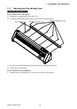
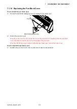
(4) Detach the pen block cover (Refer to subsection 7.1.10.).
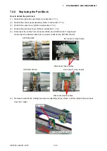
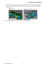
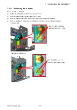
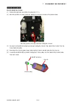
(5) Disconnect the cables from connector J3004, and J3006 on the Y-relay board.
(Disconnect the flexible cable from connector J3004 for the CE7000-130AP)
Disconnect these cables.
CE7000-40/60
Pen board (Y relay board)
CE7000-130/160
Disconnect these cables.
Pen board (Y relay board)
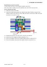
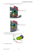
(6) Remove the two M4L6 binding head screws attaching the pen block, and then detach the pen block
from the Y slider.
M4L6 binding head screw
Pen block
Содержание CE7000-130
Страница 1: ...CE7000 UM 251 00 9370 CUTTING PLOTTER SERVICE MANUAL CE7000 40 60 130 160 130AP ...
Страница 2: ......
Страница 4: ...CE7000 UM 251 9370 II ...
Страница 72: ...CE7000 UM 251 9370 5 2 5 RECOMMENDED PARTS LIST ...
Страница 74: ......


