CE7000-UM-251-9370 VI
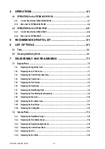
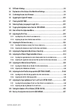
8.3 DIP Switch Settings ..............................................................................................................8-6
8.4 Explanation of the Values of the Main Board Settings ......................................................8-8
8.5 Confirming the version of firmware ....................................................................................8-9
8.6 Upgrading the System Firmware ........................................................................................8-10
8.7 Clearing the NOV-RAM ........................................................................................................8-13
8.8 Selecting Display Language & Length Unit .......................................................................8-15
8.9 Copying the Adjustment value form the SUB-NVRAM .....................................................8-16
8.10 How to Enter the Adjustment Menu ...................................................................................8-17
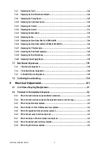
8.11 Adjusting the Pen Force ......................................................................................................8-19
8.11.1 Inputting the pen force from the recorded value ...............................................................................8-19
8.11.2 Adjusting the pen force from the measured force ........................................................................... 8-21
8.12.1 Inputting the distance accuracy from the recorded value ............................................................... 8-24
8.12.2 Adjusting the distance accuracy from the measured distance....................................................... 8-26
8.13 Adjusting the Registration Mark Sensor Sensitivity .......................................................8-29
8.14 Adjusting the Offset of Registration Mark Sensor ...........................................................8-32
8.14.1 Inputting the registration mark sensor offset position from the recorded values ........................ 8-32
8.14.2 Adjusting the registration mark sensor offset position from the measured values ..................... 8-35
8.15.1 Inputting the X Media Sensor Position from the recorded value ....................................................8-39
8.15.2 Adjusting the X Media Sensor Position .............................................................................................8-42
8.16 Adjusting the 2nd Pen Exchange position (CE7000-130AP) .......................... 8-44
8.16.1 Inputting the 2nd Pen Exchange position from the recorded value ...............................................8-44
8.16.2 Adjusting the 2nd Pen Exchange position ........................................................................................8-46
8.17.1 Inputting the Spacing Between Tool 1 and Tool 2 from the recorded value ..................................8-49
8.17.2 Adjusting the Spacing Between Tool 1 and Tool 2 ........................................................................... 8-51
8.18 Setting the Number of Push Rollers (CE7000-130/160) ....................................................8-55
8.19 Back up the adjustment value to the SUB-NVRAM .........................................................8-57
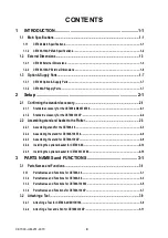
Содержание CE7000-130
Страница 1: ...CE7000 UM 251 00 9370 CUTTING PLOTTER SERVICE MANUAL CE7000 40 60 130 160 130AP ...
Страница 2: ......
Страница 4: ...CE7000 UM 251 9370 II ...
Страница 72: ...CE7000 UM 251 9370 5 2 5 RECOMMENDED PARTS LIST ...
Страница 74: ......


