


CE7000-UM-251-9370 7-53
7 DISASSEMBLY AND REASSEMBLY
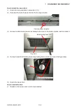
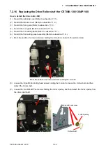
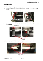
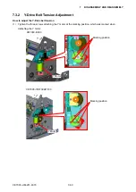
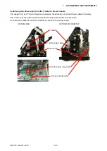
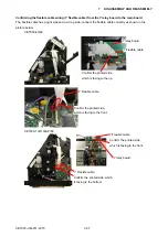
(5) Mark the position of push roller stopper as shown in the picture bellow, and then loosen the screw
holding the push roller stopper.
Mark the position of stopper here.
Stopper screw
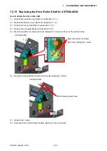
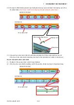
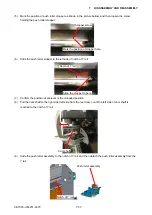
(6) Slide the push roller stopper to the left side of notch of Y rail.
Slide the stopper to here.
Notch of Y rail
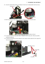
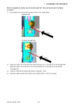
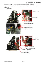
(7)
Confirm the position of set-lever is the unloaded position.
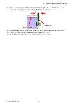
(8) Pull the cam shaft to the right side (left side from the rear view.), until the left side of cam shaft is
reached to the notch of Y rail.
Cam shaft
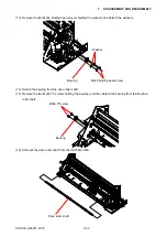
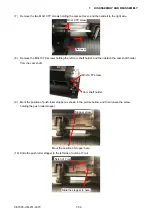
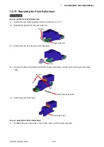
(9) Slide the push roller assembly to the notch of Y rail, and then detach the push roller assembly from the
Y rail.
Push roller assembly
Notch of Y rail
Содержание CE7000-130
Страница 1: ...CE7000 UM 251 00 9370 CUTTING PLOTTER SERVICE MANUAL CE7000 40 60 130 160 130AP ...
Страница 2: ......
Страница 4: ...CE7000 UM 251 9370 II ...
Страница 72: ...CE7000 UM 251 9370 5 2 5 RECOMMENDED PARTS LIST ...
Страница 74: ......