2–6
Overview
How the PrecisionMix II 3K Works
Usage
The standard Graco PrecisionMix II 3K
can blend most
two and three component epoxy or polyurethane
paints. The PrecisionMix is not for use with “quick-set-
ting” paints (those with a pot life of less than 15 min-
utes). For information on handling quick-setting paints
or abrasive fluids, contact your Graco distributor.
Fluid Supply
The system can be set up to mix components supplied
from pressure tanks or feed pumps. The materials can
be transferred from their original containers or from a
central paint recirculating line.
The standard PrecisionMix II 3K
is designed to operate
an air spray or air-assisted system with a capacity of
up to 2000 cc/min.
Adaptive Overrun Correction
The actual volume of fluid dispensed each cycle can
vary slightly from the calculated target. However, the
controller monitors this variance and continuously
makes adjustments to keep the ratio of Component A
to Component B and the ratio of Component C to
Component B within the user specified tolerance.
Operating Cycle
The 3K fluid manifold consists of four separate fluid
supply lines for Component A, B, C, and the flushing
material. The Component A, B, and C supply lines
have the following parts to individually control the flow
of the three materials. Refer to Fig. 2.2.
Fluid filters (D
A
, D
B
, D
C
)
Check valves (E
A
, E
B
, E
C
)
Flow meters (F
A
, F
B
, F
C
)
Dispense valves (G
A
, G
B
, G
C
)
The dispense valves control the entry of the compo-
nents into the integrator chambers. The flow meters
monitor the exact fluid volumes being dispensed and
send electrical pulses to the controller. The controller
monitors these pulses and signals the solenoids to turn
the dispense valves on or off accordingly (based on
the target volumes calculated by the controller).
Other inputs and outputs are provided to control the
purging process, signal an alarm, and interface with
the operator. Refer to Fig. 3.21, page 3–29.
The order in which the three components are mixed
depends on the characteristics of the materials being
used. In the standard configuration, Component A is
mixed with Component C first, then the blend of A and
C is mixed with Component B. The instructions in this
manual correspond with this mixing order.
To convert the PrecisionMix II 3K to a configuration
where Component A is mixed with Component B
before Component C is added, refer to
Changing the
Mixing Order,
on page 2–10.
The following is a typical ratio cycle:
Figures 2.2, 2.3, and 2.4 show the flow of fluid through
component lines A, B, and C during this cycle.
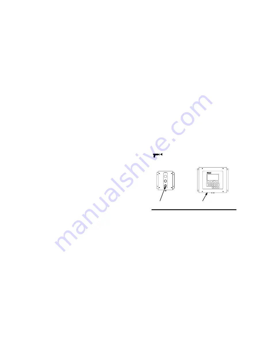
1.
To begin operation, the operator enters the desired
ratio and other parameters through the User
Interface (BB) and turns the operator switch (AA)
to MIX
.
AA
BB
Fig. 2.1
2.
When the operator triggers the spray gun, the
controller sends a signal to activate the solenoid
valve for the component A dispense valve (G
A
).
See Fig. 2.2.
3.
The component A dispense valve (G
A
) opens and
Component A begins to flow into the first integrator
chamber (L). When the correct quantity is dis-
pensed (based on the calculated target value), the
component A dispense valve closes. See Fig. 2.2.
Содержание PrecisionMix ii
Страница 6: ...6 ...
Страница 7: ...1 1 Warnings Warnings 1 ...
Страница 8: ...1 2 Warnings ...
Страница 11: ...Overview 2 1 Overview 2 ...
Страница 12: ...2 2 Overview ...
Страница 15: ...Overview 2 5 ...
Страница 31: ...Installation 3 1 Installation 3 ...
Страница 32: ...Installation 3 2 ...
Страница 58: ...Installation 3 28 Notes ...
Страница 63: ...Installation 3 33 Power up Checklist Fig 3 23 CP Interface Step 5 Step 6 Step 4 Step 7 Step 10 ...
Страница 67: ...Operation 4 1 Operation 4 ...
Страница 68: ...Operation 4 2 ...
Страница 83: ...Operation 4 17 Notes ...
Страница 90: ...Operation 4 24 ...
Страница 91: ...Screen Map 5 1 Screen Map 5 ...
Страница 92: ...5 2 Screen Map ...
Страница 94: ...5 4 Screen Map ...
Страница 95: ...Run Monitor 6 1 Run Monitor 6 ...
Страница 96: ...Run Monitor 6 2 ...
Страница 103: ...Totalizers 7 1 Totalizers 7 ...
Страница 104: ...Totalizers 7 2 ...
Страница 108: ...Totalizers 7 6 ...
Страница 109: ...System Configuration 8 1 System Configuration 8 ...
Страница 110: ...System Configuration 8 2 ...
Страница 138: ...System Configuration 8 30 PrecisionMix II 3K Robotic Interface Integrated Color Change TI0494 Fig 8 1 ...
Страница 142: ...System Configuration 8 34 ...
Страница 143: ...Recipe Setup 9 1 Recipe Setup 9 ...
Страница 144: ...Recipe Setup 9 2 ...
Страница 165: ...10 1 Troubleshooting Troubleshooting 10 ...
Страница 166: ...10 2 Troubleshooting ...
Страница 182: ...10 18 Troubleshooting ...
Страница 183: ...11 1 Service Service 11 ...
Страница 184: ...11 2 Service ...
Страница 192: ...11 10 Service ...
Страница 193: ...12 1 Parts Parts 12 ...
Страница 194: ...12 2 Parts ...
Страница 207: ...12 15 Parts Notes ...
Страница 228: ...12 36 Parts ...
Страница 229: ...13 1 Utilities Software Utilities Software 13 ...
Страница 230: ...13 2 Utilities Software ...
Страница 254: ...13 26 Utilities Software ...
Страница 255: ...14 1 Technical Data Technical Data 14 ...
Страница 256: ...14 2 Technical Data ...
Страница 259: ...14 5 Technical Data Notes ...


