11-7
Service
Service
Servicing the Operator Station
1.
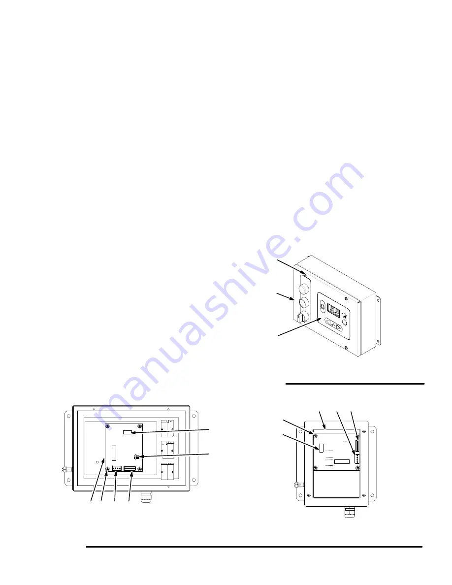
Turn the PrecisionMix II 3K power switch (D) to off.
See Fig. 11.3.
2.
While holding the operator station cover (B),
remove the 4 screws (A). See Fig. 11.7. Open the
cover, which will still be connected by one or two
cables.
To replace the station cover:
3.
Disconnect the cable from the P3 circuit board
connector. See Fig. 11.8. Disconnect the flow
control cable from the P4 connector if it is
installed.
4.
Remove the cover.
5.
Connect the cable to P3 circuit board connector on
the new cover. Connect the flow control cable to
the P4 connector if flow control is installed.
6.
Install the cover on the box, and secure it with the
4 screws (A).
To replace the circuit board:
3.
Disconnect the cable from the P2 circuit board
connector. See Fig. 11.8. Disconnect the mem-
brane switch from the P1 connector if servicing an
operator station with color change.
4.
Remove the 4 screws (C) from the circuit board.
5.
Remove the circuit board (D).
6.
If servicing an operator station with color change,
make sure the P1 slot of the new circuit board
aligns with the membrane switch. Secure the new
circuit board to the cover with the 4 screws (C).
7.
Connect the cable to the P2 circuit board connec-
tor. Connect the membrane switch to the P1
connector if servicing an operator station with color
change.
To replace the membrane on operator station with
color change:
3.
Disconnect the membrane switch from the P1
connector. See Fig. 11.8.
4.
Peel off the membrane (E) from the cover. See
Fig. 11.7. Slide the membrane switch through the
P1 slot to remove the membrane.
5.
Slide the membrane switch through the P1 slot
and install the new membrane on the cover. Con-
nect the membrane switch to the P1 connector.
Fig. 11.7
A
B
Operator Station with Color Change
E
Operator Station for One Color
Operator Station with Color Change
P4 P3
P2
Fig. 11.8
C
D
P4 P3
P2
C
D
P1
Содержание PrecisionMix ii
Страница 6: ...6 ...
Страница 7: ...1 1 Warnings Warnings 1 ...
Страница 8: ...1 2 Warnings ...
Страница 11: ...Overview 2 1 Overview 2 ...
Страница 12: ...2 2 Overview ...
Страница 15: ...Overview 2 5 ...
Страница 31: ...Installation 3 1 Installation 3 ...
Страница 32: ...Installation 3 2 ...
Страница 58: ...Installation 3 28 Notes ...
Страница 63: ...Installation 3 33 Power up Checklist Fig 3 23 CP Interface Step 5 Step 6 Step 4 Step 7 Step 10 ...
Страница 67: ...Operation 4 1 Operation 4 ...
Страница 68: ...Operation 4 2 ...
Страница 83: ...Operation 4 17 Notes ...
Страница 90: ...Operation 4 24 ...
Страница 91: ...Screen Map 5 1 Screen Map 5 ...
Страница 92: ...5 2 Screen Map ...
Страница 94: ...5 4 Screen Map ...
Страница 95: ...Run Monitor 6 1 Run Monitor 6 ...
Страница 96: ...Run Monitor 6 2 ...
Страница 103: ...Totalizers 7 1 Totalizers 7 ...
Страница 104: ...Totalizers 7 2 ...
Страница 108: ...Totalizers 7 6 ...
Страница 109: ...System Configuration 8 1 System Configuration 8 ...
Страница 110: ...System Configuration 8 2 ...
Страница 138: ...System Configuration 8 30 PrecisionMix II 3K Robotic Interface Integrated Color Change TI0494 Fig 8 1 ...
Страница 142: ...System Configuration 8 34 ...
Страница 143: ...Recipe Setup 9 1 Recipe Setup 9 ...
Страница 144: ...Recipe Setup 9 2 ...
Страница 165: ...10 1 Troubleshooting Troubleshooting 10 ...
Страница 166: ...10 2 Troubleshooting ...
Страница 182: ...10 18 Troubleshooting ...
Страница 183: ...11 1 Service Service 11 ...
Страница 184: ...11 2 Service ...
Страница 192: ...11 10 Service ...
Страница 193: ...12 1 Parts Parts 12 ...
Страница 194: ...12 2 Parts ...
Страница 207: ...12 15 Parts Notes ...
Страница 228: ...12 36 Parts ...
Страница 229: ...13 1 Utilities Software Utilities Software 13 ...
Страница 230: ...13 2 Utilities Software ...
Страница 254: ...13 26 Utilities Software ...
Страница 255: ...14 1 Technical Data Technical Data 14 ...
Страница 256: ...14 2 Technical Data ...
Страница 259: ...14 5 Technical Data Notes ...


