


Page
•
globalcontract.com
3
• Summer 2017
GLOBAL
Contract
END
LEG
SHARED
LEG
INSTALLATION GUIDELINES
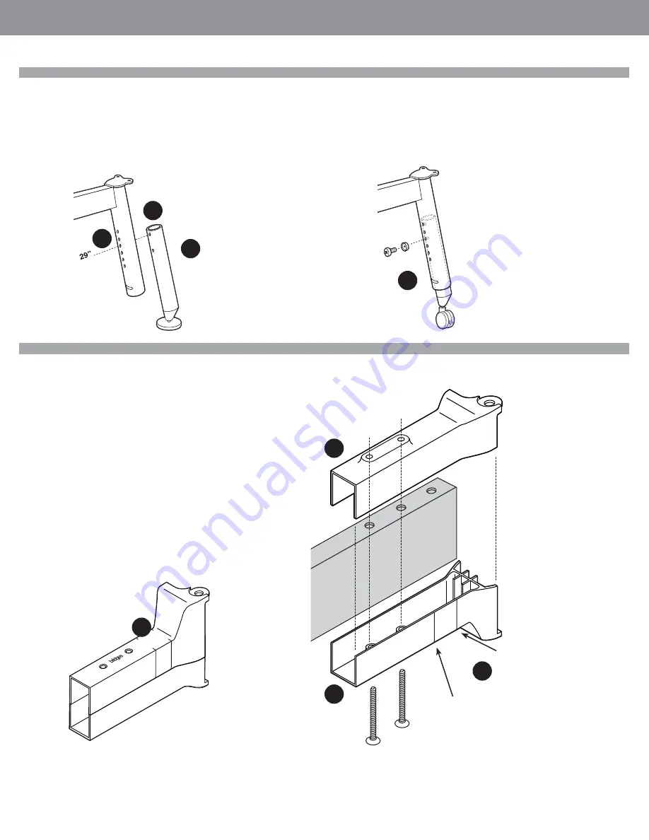
Supporting Structure Round Leg Height Adjustment
Set the legs to desired height. *
The inner leg has two threaded holes.
STEP 1: The top threaded hole is typically used to secure legs with levelers.
STEP 2: The lower threaded hole is used for securing legs with casters.
* Legs have height adjust-
ment range of 24” - 32” in 1”
increments with levelers and
27” - 35” on casters.
STEP 3: If the desired top surface height is 29” from the fl oor, for instance, and the
table structure is to be on levelers, align top threaded hole in the inner leg (1) with the
fourth hole in the table leg (3) as illustrated. When installing legs on casters, align the
lower (2) threaded hole in the inner leg with the same fourth hole (3) in the table leg
and secure with provided screws.
STEP 4: The height adjustment screws must be only used with the provided,
translucent cup/washer.
1
2
4
3
Supporting Legs And Beams
Table legs are connected to the table supporting beams with die cast aluminum
adjustable clamps. The position of these clamps on the beam establishes whether the
leg is going to be shared between two adjacent work surfaces (extended position) or
tucked under a work surface edge (retracted position).
STEP 1: Identify type and length of beam required. A single table, for instance will
have both legs tucked under the worksurface and both end brackets, therefore, will
be fully contracted. End of run table application will require one of the beam brackets
extended so that the leg it will be connected to could be shared between two adjacent
worksurfaces (while the leg on the opposite end of the beam will be tucked under the
work surface at the end of a table run. Similarly, fully extending both beam brackets
will allow both table legs to be shared.
STEP 2: In order to adjust beam bracket position, remove both countersunk Allen
head screws from the beam clamp assembly. End of supporting beam tube can be
seen through the gap between the two beam clamp parts (A). Lines on the bottom
part identify two clamp positions. Slide the top part of the clamp along the beam into
the desired position, enclose assembly with the bottom clamp part and tighten the
countersunk Allen head screws.
leg tucked under
work surface
shared leg (extended beam)
1
A
A
2


