


www.geehy.com Page 110
The two input TI1 and TI2 can be used as the interface of incremental
encoder. The counter is driven by the effective jump of the signals TI1FP1
and TI2FP2 after filtering and edge selection in TI1 and TI2.
The count pulse and direction signal are generated according to the input
signals of TI1 and TI2
The counter will count up/down according to the jumping sequence of
the input signal
Set CNTDIR of control register TMRx_CTRL1 to be read-only
(CNTDIR will be re-calculated due to jumping of any input end)
The change mechanism of counter count direction is shown in the figure below
Table 43 Relationship between Count Direction and Encoder
Effective edge
Count only in TI1
Count only in TI2
Count in both TI1 and
TI2
Level of relative signal
High
Low
High
Low
High
Low
TI1FP1
Rising edge
—
Count
down
Count up
Count
down
Count up
Falling edge
Count up
Count
down
Count up
Count
down
TI2FP2
Rising edge
Count up
Count
down
—
Count up
Count
down
Falling edge
Count
down
Count up
Count
down
Count up
The external incremental encoder can be directly connected with MCU, not
needing external interface logic, so the comparator is used to convert the
differential output of the encoder to digital signal to increase the immunity from
noise interference.
Among the following examples,
IC1FP1 is mapped to TI1
IC2FP2 is mapped to TI2
Neither IC1FP1 nor IC2FP2 is reverse phase
The input signal is valid at the rising edge and falling edge
Enable the counter
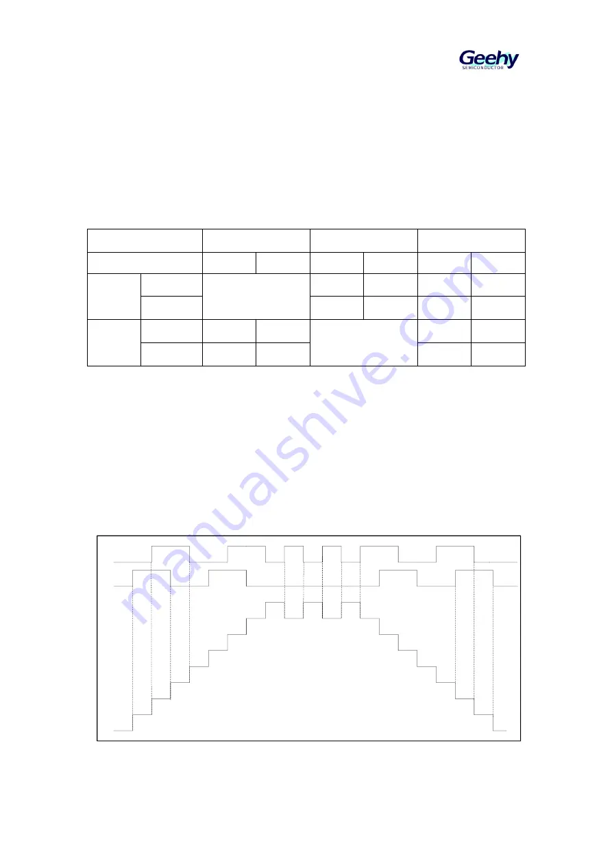
Figure 38 Counter Operation Example in Encoder Mode
TI1
TI2
Counter
For example, when TI1 is at low level, and TI2 is in rising edge state, the counter will count
up.


