SECTION 4: Repair
2025653-048 Revision B
Responder
™
2000
Page 37
Assembly Step
Details
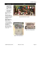
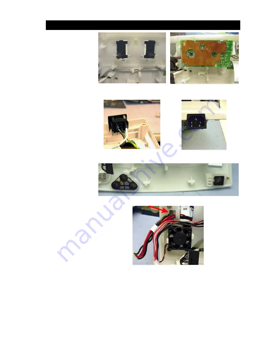
Snap the two black
Brackets
into place on the
Lower Frame
.
Note:
Check the
Power
Supply
green ground wire
to ensure it is properly
soldered on both ends and
is in good condition.
Place the
Power Supply
on
the
Brackets
.
Note:
The
Power Supply
is
not secured until the
Base
Cover
is installed.
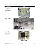
Figure 24: Brackets Installed
Figure 25: Power Supply Installed
Place the
AC Cable
Connector
into the
Lower
Frame
as shown.
Note:
The single ground pin
must be at the top.
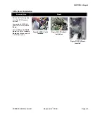
Figure 26: AC Cable Connector
Figure 27: Proper Connector
Orientation
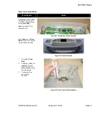
Insert the
Power Button
and
Control Button
assemblies into the
Lower
Frame
.
Figure 28: Power and Control Button Assemblies Installed
Pass
Therapy Power
Cable
into the
Lower
Frame
as shown. Pull the
slack through, leaving
enough length to connect to
Power Control Board
(installed in the next step).
Figure 29: Therapy Power Cable
Содержание Responder 2000
Страница 1: ...TM...
Страница 10: ...SECTION 1 Introduction 2025653 048 Revision B Responder 2000 Page 10 Controls and Indicators...
Страница 137: ...Contact Information 2025653 048 Revision B Responder 2000 Page 137 END OF DOCUMENT LAST PAGE...
Страница 138: ...TM...

