


SECTION 4: Repair
2025653-048 Revision B
Responder
™
2000
Page 40
ECG Board Installation
Assembly Step
Details
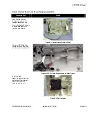
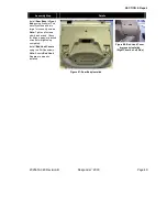
Install the
ECG Insulator
in
the
Front Body
.
Figure 39: ECG Insulator Installed
Install the
ECG Board
to
the
Front Body
by
connecting
J412
on the
ECG Board
to
J212
on the
Main Board
.
Install the seven Phillips
screws to hold the
ECG
Board
in place.
Figure 40: ECG Board Installed
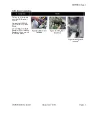
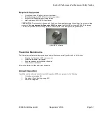
Connect the ECG cable to
the
ECG Board
.
•
J4231 White
•
J4232 Black
•
J4233 Red
•
J4234 Brown
•
J4235 Green
•
J4236 Gray
Notes:
Gently pull on each
connector to ensure it is
locked in place.
The extra gray connector
will be connected later.
Figure 41: ECG Cable Installation Detail
Содержание Responder 2000
Страница 1: ...TM...
Страница 10: ...SECTION 1 Introduction 2025653 048 Revision B Responder 2000 Page 10 Controls and Indicators...
Страница 137: ...Contact Information 2025653 048 Revision B Responder 2000 Page 137 END OF DOCUMENT LAST PAGE...
Страница 138: ...TM...