


SECTION 4: Repair
2025653-048 Revision B
Responder
™
2000
Page 42
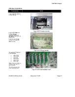
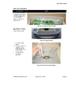
Display Installation
Assembly Step
Details
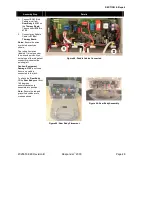
If necessary, snap the
LCD
into the
LCD Retainer
.
Connect the LCD ribbon
cable to
J214
on the
Main
Board
.
Note:
See the Ribbon
Cable Installation Notes for
proper installation (Figures
6, 7 and 8).
Secure the
LCD
to the
Front Body
with five
Phillips screws (two in front,
three in back).
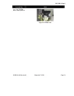
Figure 42: LCD Installed in LCD
Retainer
Figure 43: LCD Screw Locations
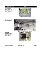
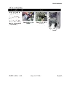
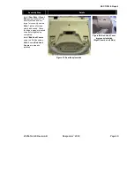
Connect the LCD backlight
cable to
J213
on the
Main
Board
.
Note:
Twist the cable 9 to
15 times and fold it over the
LCD Retainer
as shown.
Remove the protective film
from the
LCD
.
Caution: Equipment
Damage.
Do not touch the
front of the LCD.
Figure 44: LCD Backlight Cable
(Properly Routed)
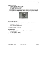
Caution: Shock Hazard or Equipment Damage.
The Responder 2000 is energized
for the following step to verify proper operation. Exposed circuit boards may contain
potentially dangerous voltages. Do not touch exposed electronics and keep all tools
clear while performing the verification.
At this point the assembly may be verified by connecting AC Power and turning on the
unit. The display should be clear and bright. When the check is complete, turn the
power off and disconnect the AC power cord.
Note:
This test will cause a service code error because the
Therapy board
is not
installed. Delete this error when reassembly is complete.
Содержание Responder 2000
Страница 1: ...TM...
Страница 10: ...SECTION 1 Introduction 2025653 048 Revision B Responder 2000 Page 10 Controls and Indicators...
Страница 137: ...Contact Information 2025653 048 Revision B Responder 2000 Page 137 END OF DOCUMENT LAST PAGE...
Страница 138: ...TM...