background image

Pilot’s Guide for the Cirrus SR2x with Cirrus Perspective by Garmin

190-00820-11  Rev. A

SY

STEM

O

VER

VIEW

FLIGHT

INSTRUMENTS

EIS

AUDIO P

ANEL

& CNS

FLIGHT

MANA

GEMENT

HAZARD

AV

OID

ANCE

AFCS

ADDITIONAL FEA

TURES

APPENDICES

INDEX

678

APPENDIX A

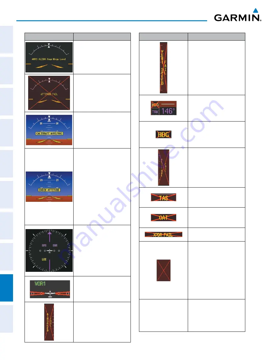
System Annunciation

Comment

Attitude and Heading 
Reference System is aligning.

Display system is not receiving 
attitude information from the 
AHRS.

AHRS calibration incomplete or 
configuration module failure.

This annunciation is seen only 
when the autopilot is engaged.  
The annunciation indicates an 
AHRS monitor has detected 
an abnormal flight parameter, 
possibly caused by strong 
turbulence.  In this case, the 
situation should correct itself 
within a few seconds.  If there 
is an actual failure, a red “X” 
soon appears over the Attitude 
Indicator.
GPS information is either 
not present or is invalid for 
navigation use.  Note that 
AHRS utilizes GPS inputs 
during normal operation.  
AHRS operation may be 
degraded if GPS signals are not 
present (see POH).

CDI is not receiving valid data 
from the corresponding GIA.  
Does not apply when the CDI is 
set to GPS. 

Display system is not receiving 
airspeed input from air data 
computer.

System Annunciation

Comment

Display system is not receiving 
vertical speed input from the 
air data computer.

System is not receiving valid 
heading input from GMU, but 
is receiving GPS-derived track 
information.
System is not receiving valid 
heading input from GMU and 
is not receiving GPS-derived 
track information.

Display system is not receiving 
altitude input from the air data 
computer.

Display system is not receiving 
valid true airspeed information 
from air data computer.
Display system is not receiving 
valid OAT information from air 
data computer.
Display system is not receiving 
valid transponder information.
Different versions of GDU 
software are installed in the 
PFD and MFD.  This can also 
indicate different versions 
of the navigation database 
installed in the PFD and MFD.  
A cross-talk error between the 
PFD and MFD will also cause 
this annunciation.

Other Various Red X 

Indications

A red ‘X’ through any other 
display field (such as engine 
instrumentation fields) 
indicates that the field is not 
receiving valid data.

Содержание CIRRUS PERSPECTIVE SR2x

Страница 1: ...6062 U S A p 913 397 8200 f 913 397 8282 www garmin com Garmin AT Inc 2345 Turner Road SE Salem OR 97302 U S A p 503 391 3411 f 503 364 2138 Garmin Europe Ltd Liberty House Hounsdown Business Park Sou...

Страница 2: ......

Страница 3: ...SYSTEM OVERVIEW FLIGHT INSTRUMENTS ENGINE INDICATION SYSTEM AUDIO PANEL CNS FLIGHT MANAGEMENT HAZARD AVOIDANCE AUTOMATIC FLIGHT CONTROL SYSTEM ADDITIONAL FEATURES APPENDICES INDEX...

Страница 4: ...ereby grants permission to download a single copy of this manual and of any revision to this manual onto a hard drive or other electronic storage medium to be viewed for personal use provided that suc...

Страница 5: ...anizations expressly disclaim all warranties with respect to the AC U KWIK information included in this data express or implied including but not limited to the implied warranties of merchantability a...

Страница 6: ...Pilot s Guide for the Cirrus SR2x with Cirrus Perspective by Garmin 190 00820 11 Rev A Blank Page...

Страница 7: ...not use basemap land and water data information for primary navigation Basemap data is intended only to supplement other approved navigation data sources and should be considered as an aid to enhance...

Страница 8: ...y discrepancies before continuing navigation WARNING Lamp s inside this product may contain mercury HG and must be recycled or disposed of according to local state or federal laws For more information...

Страница 9: ...ence that may cause undesired operation NOTE Interference from GPS repeaters operating inside nearby hangars can cause an intermittent loss of attitude and heading displays while the aircraft is on th...

Страница 10: ...lecting Database Exclusions List NOTE The pilot operator must have access to Garmin and Jeppesen database alerts and consider their impact on the intended aircraft operation The database alerts can be...

Страница 11: ...820 03 A 6 30 09 i I 6 Added AOPA Airport Directory Added dual navigation database capability Added database synchronization Added other GDU 10 00 parameters 190 00820 04 A 2 28 10 i I 6 Added the SR2...

Страница 12: ...aft alerts Added AC U KWIK airport directory Added other GDU 12 11 parameters 190 00820 09 B 01 29 2013 i I 6 Updated Advisory Alerts table Made clerical changes 190 00820 10 A 01 24 2014 i I 6 Added...

Страница 13: ...er Beacon Annunciations 84 Traffic Annunciation 84 Terrain Annunciations 85 Altitude Alerting 85 Low Altitude Annunciation 86 Minimum Descent Altitude Decision Height Alerting 86 2 4 Abnormal Operatio...

Страница 14: ...Fuel Range Ring 188 Field of View SVS 189 Selected Altitude Intercept Arc 190 Destination Airport Information 191 5 3 Waypoints 192 Airports 193 Intersections 200 NDBs 202 VORs 204 User Waypoints 206...

Страница 15: ...ng Traffic Information 471 Altitude Display 474 Traffic Map Page Display Range 474 TAS Alerts 476 System Status 476 6 12 Garmin GDL 88 ADS B Traffic 478 ADS B System Overview 478 ADS B with TAS 480 Co...

Страница 16: ...d Protection ESP 654 Roll Engagement 655 Pitch Engagement 656 Low Speed Protection 658 High Airspeed Protection 658 8 15 Position Reporting 659 8 16 Bluetooth Management 662 8 17 Abnormal Operation 66...

Страница 17: ...63W Integrated Avionics Unit GMA 347 350 Audio Panel with Integrated Marker Beacon Receiver GMC 705 AFCS Control Unit if the Garmin Automatic Flight Control System AFCS is installed GMU 44 Magnetomete...

Страница 18: ...connection GDU 1240A 20 1040A 20 1 This unit is configured as a MFD that features a 12 or 10 4 inch LCD with 1024 x 768 resolution The unit installed on the right copilot side is designated as MFD Thi...

Страница 19: ...nals from the engine and airframe sensors This unit communicates with both GIA 63Ws using an RS 485 digital interface GRS 77 1 or 2 The Attitude and Heading Reference System AHRS provides aircraft att...

Страница 20: ...lity The GTX 33 may also be additionally be equipped with 1090 MHz Extended Squitter 1090ES transmit capability The PFD provides transponder controls The transponder communicates with the primary GIA...

Страница 21: ...lephone voice communication by means of pilot and copilot headsets The unit can also send and receive data over the Iridium satellite network The GSR 56 is connected to the optional GDL 59 with an RS...

Страница 22: ...terface with each GIA 63W The GSM 85A 86 servo gearbox is responsible for transferring the output torque of the GSA 80 81 servo actuator to the mechanical flight control surface linkage GTA 82 1 optio...

Страница 23: ...2 Pitch Trim GRS 77 1 GIA 63W 1 GMC 705 GMU 44 1 GEA 71 1 GDC 74A 1 GTP 59 1 GMA 350 or GMA 347 optional GCU 478 GDL 69 69A GRS 77 2 GMU 44 2 GDC 74A 2 VHF COM VHF NAV LOC GPS WAAS G S AFCS Mode Logic...

Страница 24: ...2 SYSTEM CONTROLS NOTE The Audio Panel GMA 347 and AFCS controls GMC 705 are described in the Audio Panel CNS and AFCS sections respectively The system controls are located on the PFD and MFD bezels P...

Страница 25: ...proach procedures IAPs for a flight plan If a flight plan is used available procedures for the departure and or arrival airport are automatically suggested These procedures can then be loaded into the...

Страница 26: ...ser to enter a destination waypoint and establish a direct course to the selected destination the destination is either specified by the identifier chosen from the active route or taken from the map p...

Страница 27: ...ht Plan Page on the MFD alphanumeric keys can be used to enter data into the Quick Select Box area 15 Plus Minus Key Toggles a or character 16 Decimal Key Enters a decimal point 17 BKSP Key Moves the...

Страница 28: ...ages disengages the autopilot 4 LVL Key Engages the autopilot if the autopilot is disengaged and the aircraft is within the autopilot engagement limitations in level vertical and lateral modes NOTE Th...

Страница 29: ...the AFCS section GMA 350 350C AUDIO PANEL CONTROLS GMA 350 Controls 21 14 15 17 12 13 11 19 20 18 16 10 8 6 4 2 3 5 7 9 1 GMA 350c Bluetooth Controls 22 24 25 26 23 Figure 1 5 GMA 350 350c Audio Pane...

Страница 30: ...Jack Used for an entertainment or telephone input 12 MIC1 Selects the 1 transmitter for transmitting COM1 receive is simultaneously selected when this key is pressed allowing received audio from the 1...

Страница 31: ...Bluetooth audio can only be assigned to one source at a time Once the Bluetooth audio is assigned to an audio source the remaining entertainment audio sources will only cycle between OFF and WHITE 24...

Страница 32: ...cted audio from the 1 COM receiver can be heard 4 COM2 When selected audio from the 2 COM receiver can be heard 5 COM3 Reserved for optional COM radio 6 NAV1 When selected audio from the 1 NAV receive...

Страница 33: ...e heard COM2 receive can be added by pressing the COM2 Key 17 COM2 MIC Selects the 2 transmitter for transmitting COM2 receive is simultaneously selected when this key is pressed allowing received aud...

Страница 34: ...unctions including GPS NAV terrain traffic and weather data optional Each softkey sublevel has a BACK Softkey which can be selected to return to the previous level The ALERTS Softkey is visible at all...

Страница 35: ...e aircraft NEXRAD C or PRECIP Displays SiriusXM NEXRAD C weather and coverage on Inset Map optional When the GDL 88 is installed and FIS B is the selected weather source softkey cycles through NEXRAD...

Страница 36: ...AHRS AHRS2 Selects the optional 2 AHRS Figure 1 11 First PFD Softkey Level Press the BACK Softkey to return to the top level softkeys XPDR STBY ON ALT VFR IDENT BACK ALERTS CODE GND STD BARO BACK ALE...

Страница 37: ...e Flight Path Marker when SVT is disabled HRZN HDG must be enabled DFLTS Resets PFD to default settings including changing units to standard AOA and Wind Softkeys shown if optional Angle of Attack Sen...

Страница 38: ...n arc format ALT UNIT Displays softkeys for setting the altimeter and BARO settings to metric units METERS When enabled displays altimeter in meters IN Select to display the BARO setting as inches of...

Страница 39: ...s ON Selects Mode A transponder replies to interrogations ALT Selects Mode C Altitude Reporting Mode transponder replies to identification and altitude interrogations VFR Automatically enters the VFR...

Страница 40: ...s This option is only available on SR22 models Figure 1 13 MFD Softkeys CHKLIST DCLTR ENGINE DCLTR 2 DCLTR 3 DCLTR 1 MAP The DONE Softkey label changes to UNDO when the checklist item is already check...

Страница 41: ...ENTER Saves the usable fuel amount shown on the Initial Usable Fuel Page MAP Enables second level Navigation Map softkeys TRAFFIC Displays traffic information on Navigation Map PROFILE Displays remove...

Страница 42: ...avigation Map optional LEGEND Displays the legend for the selected weather products Available only when NEXRAD XM LTNG and or METAR softkeys are selected BACK Returns to top level softkeys DCLTR 3 Sel...

Страница 43: ...illuminated on the audio panels the control units and the display bezels On the PFD the AHRS initializes and displays AHRS ALIGN Keep Wings Level The AHRS should display valid attitude and heading fi...

Страница 44: ...al operating mode backlighting can only be adjusted from the PFD or from any display operating in reversionary mode In normal operating mode the PFD presents graphical flight instrumentation attitude...

Страница 45: ...U display Ethernet interface is cut off Thus the IAU can no longer communicate with the remaining display refer to Figure 1 1 and the NAV and COM functions provided to the failed display by the IAU ar...

Страница 46: ...nt begins to initialize All instruments should be operational within one minute of power up If any instrument remains flagged the system should be serviced by a Garmin authorized repair facility NOTE...

Страница 47: ...h which the FMS Knob can be used to scroll information within the selected window Pressing the MFD1 DB Softkey label background changes to grey indicting the softkey is selected places the cursor in t...

Страница 48: ...ata Available and Reliable Y E S N O Mag Data AND Air Data Available and Reliable GPS Data Available and Reliable Figure 1 20 AHRS Operation Loss of GPS magnetometer or air data inputs is communicated...

Страница 49: ...le Failure to update this database could lead to erroneous heading information being displayed to the pilot GPS RECEIVER OPERATION Each GIA 63W Integrated Avionics Unit IAU contains a GPS receiver Inf...

Страница 50: ...e MFD to select the Auxiliary Page Group see Section 1 6 for information on navigating MFD page groups 2 Turn the small FMS Knob to select AUX GPS Status Page 3 To change the selected GPS receiver Pre...

Страница 51: ...layed below the satellite signal accuracy measurements GPS receiver status The GPS solution type ACQUIRING 2D NAV 2D DIFF NAV 3D NAV 3D DIFF NAV for the active GPS receiver GPS1 or GPS2 is shown in th...

Страница 52: ...r a Use the large FMS Knob to scroll to the Most Recent Waypoints List b Use the small FMS Knob to highlight the desired waypoint in the list and press the ENT Key The system automatically fills in th...

Страница 53: ...g Disabling WAAS EGNOS or MSAS 1 Select the GPS Status Page 2 If necessary press the SBAS Softkey 3 Press the FMS Knob and turn the large FMS Knob to highlight the desired SBAS system 4 Press the ENT...

Страница 54: ...ayed window page There is no all encompassing menu Some menus provide access to additional submenus that are used to view edit select and review options Menus display No Options when there are no addi...

Страница 55: ...t Procedures Weather Information XM Procedure Loading the active title of the page changes while the page name in the list remains the same Figure 1 25 Page Title and Page Groups Page Group Active Pag...

Страница 56: ...l Weather Data Link services optional Terrain Proximity Terrain SVS optional TAWS B optional Figure 1 27 Waypoint Pages Airport Procedures Weather Information Pages Waypoint Pages WPT Airport Procedur...

Страница 57: ...Auxiliary Pages AUX Trip Planning Utility GPS Status System Setup Page s SiriusXM P ages optional XM Radio RADIO Softkey XM Information INFO Softkey Satellite Phone Pages optional Telephone TEL Softk...

Страница 58: ...can also be accessed using the FPL Key on the PFD MFD Control Unit Main pages within this group are then selected by pressing the FMS Key and turning the FMS Knobs In some instances softkeys may be u...

Страница 59: ...t Instruments Section Baro Transition alert see Flight Instruments Section Airspace alerts see Flight Management Section Audio Alert Voice Page Navigation Settings MFD Navigation Data Bar Fields see F...

Страница 60: ...1 32 AUX System Setup Page DATE TIME The system obtains the current Coordinated Universal Time UTC date and time directly from the GPS satellite signals shown on the AUX GPS Status Page Figure 1 22 Sy...

Страница 61: ...ighlight the Time Format field 4 Turn the small FMS Knob to select the desired format and press the ENT Key to confirm selection The Time Offset field is highlighted 5 Use the FMS Knob to enter the de...

Страница 62: ...Navigation Status Box All distances on MFD Altitude buffer distance System Setup All speeds on MFD Airspeed Indicator True Airspeed PFD Ground Speed PFD Wind speed vector Map range Traffic Page Terrai...

Страница 63: ...Profiles AUX System Setup Page Creating a profile 1 Use the FMS Knob to select the AUX System Setup Page 2 Press the FMS Knob momentarily to activate the flashing cursor 3 Turn the large FMS Knob to...

Страница 64: ...the FMS Knob to enter a new profile name up to 16 characters long and press the ENT Key 8 With RENAME highlighted press the ENT Key 9 To cancel the process use the large FMS Knob to select CANCEL and...

Страница 65: ...d small FMS Knobs to enter the name and press the ENT Key Imported profile names cannot begin with a blank space or be named DEFAULT GARMIN DEFAULTS or DEFAULT SETTINGS 6 With IMPORT highlighted press...

Страница 66: ...NT Key with EXPORT highlighted To change the profile file name turn the large FMS Knob to highlight the SELECT FILE field then enter the new name with the large and small FMS Knobs then press the ENT...

Страница 67: ...he Page Group Tabs and navigates to the next tab with one click of the large FMS Knob The pilot can select from the AUX System Setup Page the amount of time the Page Group Tabs are displayed in the lo...

Страница 68: ...mer PFD 1 Press the TMR REF Softkey 2 Turn the large FMS Knob to select the timer field hh mm ss 3 Use the FMS Knob to enter the desired time and press the ENT Key 4 With the UP DN field highlighted t...

Страница 69: ...RESET highlighted The field changes back to START and the digits are reset Figure 1 41 Timers AUX Utility Page Setting the flight timer starting criterion 1 Use the FMS Knob to select the AUX Utility...

Страница 70: ...to highlight Reset Departure Time and press the ENT Key GPS POSITION The Timer References Window on the PFD shows the current GPS position at the bottom of the window using the selected display format...

Страница 71: ...can be adjusted from the remaining display Adjusting display backlighting 1 Press the PFD MENU Key to display the PFD Setup Menu AUTO is now highlighted next to PFD DSPL 2 Turn the small FMS Knob to s...

Страница 72: ...s and are located on the top right portion of the display bezels Each display bezel is equipped with two SD card slots The system uses SD cards to store databases such as terrain or charts in addition...

Страница 73: ...ourse deviation information In addition to the flight instruments navigation communication terrain traffic and weather information are also presented on the PFD and explained in other sections of this...

Страница 74: ...Horizontal Situation Indicator HSI 7 Course Deviation Indicator CDI 8 Outside Air Temperature OAT 9 Softkeys 10 System Time 11 Transponder Status Box 12 Selected Heading Bug 13 Turn Rate Indicator 14...

Страница 75: ...ES APPENDICES INDEX 1 Traffic Annunciation 2 Selected Heading 3 Wind Data 4 Inset Map 5 DME Information Window 6 Bearing 1 Information Window 7 Selected Course 8 Barometric Minimums Box 9 Flight Plan...

Страница 76: ...inter remains black until reaching the never exceed speed VNE at which point it turns red The true airspeed is displayed in knots below the Airspeed Indicator The Ground Speed appears in knots to the...

Страница 77: ...failure Vspeeds Glide VR VX and VY bugs can be turned on off from the Timer References Window VR is categorized as a takeoff Vspeed When active on the Vspeeds are displayed at their respective locati...

Страница 78: ...25 below and 45 above the horizon line Between 20 below to 20 above the horizon line minor pitch marks occur every 2 5 When the optional Synthetic Vision Technology SVT system is activated the pitch...

Страница 79: ...e Selected Altitude When a Selected Altitude is set a light blue Selected Altitude Intercept Arc if enabled is displayed on the navigation maps when the aircraft is climbing or descending This arc app...

Страница 80: ...are selected Adjusting the altimeter barometric pressure setting creates discontinuities in VNV vertical navigation moving the descent path For large adjustments it may take several minutes for the ai...

Страница 81: ...ert OFF or ON and press the ENT Key 5 With the altitude field highlighted turn the small FMS Knob to set desired altitude and press the ENT Key 6 To cancel the selection press the FMS Knob Figure 2 9...

Страница 82: ...ideslope needle on a conventional indicator If a localizer frequency is tuned and there is no glideslope NO GS is displayed in place of the diamond NOTE The Glidepath Indicator appears on the display...

Страница 83: ...nd is available in two formats 360 compass rose and 140 arc Changing the HSI display format 1 Press the PFD Softkey 2 Press the HSI FRMT Softkey 3 Press the 360 HSI or ARC HSI Softkey The 360 HSI cont...

Страница 84: ...cted Heading is shown to the upper left of the HSI for 3 seconds after being adjusted The light blue bug on the compass rose corresponds to the Selected Heading While the HSI is displayed as an arc if...

Страница 85: ...een loaded into the flight plan the system generates a message to change the navigation angle setting to True at the appropriate time Figure 2 16 Heading and Course Indications True Changing the navig...

Страница 86: ...lid Arrow Shown for Turn Rate 4 deg sec Half standard Turn Rate Standard Turn Rate Figure 2 18 Turn Rate Indicator and Trend Vector BEARING POINTERS AND INFORMATION WINDOWS NOTE When the Arc HSI is di...

Страница 87: ...bearing pointer is removed from the HSI and NO DATA is displayed in the information window if The NAV radio is not receiving the tuned VOR station GPS is the bearing source and an active waypoint is n...

Страница 88: ...ion Indicator Arc HSI Navigation Source Flight Phase CDI CDI Scale Navigation Source CDI Crosstrack Error Scale Flight Phase 360 HSI The CDI can display two sources of navigation GPS or NAV VOR locali...

Страница 89: ...rces GPS Selected NAV1 Selected for Tuning LOC1 Selected NAV2 Selected for Tuning VOR2 Selected The system automatically switches from GPS to LOC navigation source and changes the CDI scaling accordin...

Страница 90: ...n setting may also be changed 2 0 nm 1 0 nm 0 3 nm or Auto from this page If the selected scaling is smaller than the automatic setting for enroute and terminal phases the CDI is scaled accordingly an...

Страница 91: ...t departure waypoint if more than 30 nm from the departure airport or the leg after the last departure waypoint has been activated or a direct to waypoint is activated If after completing the departur...

Страница 92: ...ated the CDI scale changes to 0 3 nm The system automatically switches back to terminal mode under the following conditions The next leg in the missed approach procedure is not aligned with the final...

Страница 93: ...s enabled a course line is drawn through the active to waypoint on the moving map If desired the course to from the waypoint can now be adjusted When OBS Mode is disabled the GPS flight plan returns t...

Страница 94: ...aircraft crosses the missed approach point MAP automatic approach waypoint sequencing is suspended SUSP appears on the HSI at the lower right of the aircraft symbol The OBS Softkey label changes to in...

Страница 95: ...he Inset Map and wind data display In addition to the flight instruments the PFD also displays various supplemental information including temperatures wind data and Vertical Navigation VNV indications...

Страница 96: ...ng temperature display units 1 Select the AUX System Setup Page on the MFD using the FMS Knob 2 Press the FMS Knob to activate the cursor 3 Turn the large FMS Knob to highlight the TEMP field in the D...

Страница 97: ...is invalid or unavailable the window displays NO WIND DATA Wind data can be displayed in two different ways Figure 2 31 Wind Data No Data Option 1 Option 2 Displaying wind data 1 Press the PFD Softke...

Страница 98: ...lect the auto mode In auto mode the AOA Indicator appears when the landing gear is down and locked or the flaps position is three degrees or greater Otherwise the AOA Indicator is removed Figure 2 40...

Страница 99: ...rtical Deviation VDI VNV Target Altitude Aircraft 1 min before the next TOD due to flight plan change X X X VNV cancelled CNCL VNV Softkey pressed on MFD X X X Distance to active waypoint cannot be co...

Страница 100: ...Beacon Annunciations Inner Marker Middle Marker Outer Marker Altimeter TRAFFIC ANNUNCIATION The Perspective system displays traffic symbolically on the Inset Map PFD the Navigation Map Page MFD and v...

Страница 101: ...e Selected Altitude Whenever the Selected Altitude is changed the Altitude Alerter is reset The Altitude Alerter is independent of the Garmin AFCS The following occur when approaching the Selected Alt...

Страница 102: ...ltimeter Low Altitude Annunciation MINIMUM DESCENT ALTITUDE DECISION HEIGHT ALERTING For altitude awareness a Minimum Descent Altitude MDA or Decision Height DH based on barometric altitude or tempera...

Страница 103: ...ug 1 Press the TMR REF Softkey 2 Turn the large FMS Knob to highlight the Minimums field 3 Turn the small FMS Knob to select the desired altitude source barometric BARO or temperature compensated TEMP...

Страница 104: ...dReckoning SystemisusingprojectedpositionratherthanGPSposition to compute navigation data and sequence active flight plan waypoints Table 2 3 Abnormal GPS Conditions Annunciated on HSI Figure 2 41 Exa...

Страница 105: ...ber HDG annunciation with a red X appear above the TRK annunciation to indicate the HSI is displaying track instead of heading If both the heading and track are unavailable the HSI displays an amber H...

Страница 106: ...during such situations The following information is removed from the PFD and corresponding softkeys are disabled when the aircraft experiences unusual attitudes Traffic Annunciations AFCS Annunciatio...

Страница 107: ...he display combines Primary Flight Display PFD symbology with the EIS EIS Display Figure 3 1 MFD SR20 Green bands on the instruments indicate normal ranges of operation amber and red bands indicate ca...

Страница 108: ...t fuel flow indicator to the right of the fuel flow indicator strip shown in Figure 3 4 5 Gallons Used Indicator Gal Used Displays the fuel used in gallons 6 Oil Temperature Indicator Oil F Displays e...

Страница 109: ...e by Garmin 93 ENGINE INDICATION SYSTEM SYSTEM OVERVIEW FLIGHT INSTRUMENTS EIS AUDIO PANEL CNS FLIGHT MANAGEMENT HAZARD AVOIDANCE AFCS ADDITIONAL FEATURES APPENDICES INDEX Figure 3 2 EIS Display SR18...

Страница 110: ...EM SYSTEM OVERVIEW FLIGHT INSTRUMENTS EIS AUDIO PANEL CNS FLIGHT MANAGEMENT HAZARD AVOIDANCE AFCS ADDITIONAL FEATURES APPENDICES INDEX Figure 3 4 EIS Display SR22 SR22 Naturally Aspirated 6 9 4 3 2 1...

Страница 111: ...or ENTER Softkey to return to the second level softkeys BACK ENGINE FUEL ASSIST ENGINE DCLTR ANTI ICE Optional UNDO FULL TABS ENTER The ANTI ICE Softkey and its second level softkeys are only availab...

Страница 112: ...range in nautical miles and economy in nautical miles per gallon based on the displayed fuel remaining and the fuel flow totalizer 8 Fuel Quantity Indicator Displays fuel quantities in gallons for the...

Страница 113: ...e by Garmin 97 ENGINE INDICATION SYSTEM SYSTEM OVERVIEW FLIGHT INSTRUMENTS EIS AUDIO PANEL CNS FLIGHT MANAGEMENT HAZARD AVOIDANCE AFCS ADDITIONAL FEATURES APPENDICES INDEX 12 4 Figure 3 6 Engine Page...

Страница 114: ...STEM OVERVIEW FLIGHT INSTRUMENTS EIS AUDIO PANEL CNS FLIGHT MANAGEMENT HAZARD AVOIDANCE AFCS ADDITIONAL FEATURES APPENDICES INDEX 1 12 9 3 2 6 4 5 7 Figure 3 8 Engine Page SR22 with TKS NH Anti Ice Op...

Страница 115: ...Range and economy Econ are calculated based on the displayed fuel remaining Rem and the fuel flow totalizer The calculated range is based upon ground speed distance economy and fuel remaining See the...

Страница 116: ...M OVERVIEW FLIGHT INSTRUMENTS EIS AUDIO PANEL CNS FLIGHT MANAGEMENT HAZARD AVOIDANCE AFCS ADDITIONAL FEATURES APPENDICES INDEX Figure 3 12 Full Fuel SR18 Initial Usable Fuel Page Change in Fuel Level...

Страница 117: ...OVERVIEW FLIGHT INSTRUMENTS EIS AUDIO PANEL CNS FLIGHT MANAGEMENT HAZARD AVOIDANCE AFCS ADDITIONAL FEATURES APPENDICES INDEX Figure 3 14 Fuel to TABS SR22 Initial Usable Fuel Page Change in Fuel Leve...

Страница 118: ...or located on the full Engine Page To accommodate the additional modes the TKS FIKI system employs several additional sensors The Perspective System receives inputs from these sensors and provides ind...

Страница 119: ...tity indicator is marked with a red X Figure 3 19 Figure 3 18 Fluid Level Unreliable Figure 3 19 Fluid Level Out Of Range Manual Tank Mode Manual tank mode allows the pilot to control either tank s sh...

Страница 120: ...odes selected NORM Both pumps operate on a timed repeating cycle 30 seconds ON and 90 seconds OFF Provides 50 flow rate for light moderate icing HIGH A single pump 1 operates continuously Provides 100...

Страница 121: ...peaks When the ASSIST Softkey is pressed the system initially highlights the number and places a cyan box around the EGT display of the cylinder with the hottest EGT The Peak temperature is the diffe...

Страница 122: ...ystem Overview for information about display Reversionary Mode In reversionary mode the EIS is separated into two displays Engine identical to the normal EIS Display on the MFD and System For a descri...

Страница 123: ...System Display 1 Press the ENGINE Softkey 2 Press the SYSTEM Softkey 3 To return to the default Engine Display press the ENGINE or BACK Softkey 1 Percent Power Indicator Pwr Displays engine power as...

Страница 124: ...1 Rev A 108 ENGINE INDICATION SYSTEM SYSTEM OVERVIEW FLIGHT INSTRUMENTS EIS AUDIO PANEL CNS FLIGHT MANAGEMENT HAZARD AVOIDANCE AFCS ADDITIONAL FEATURES APPENDICES INDEX Figure 3 28 System Display 6 4...

Страница 125: ...Unit 2 Audio Panel Mode A C or Mode S Transponder Control Unit The MFD PFD controls are used to tune the communication transceivers and navigation radios The Audio Panel provides the traditional audi...

Страница 126: ...M Knob Tunes the standby frequencies for the COM transceiver large knob for MHz small knob for kHz Press to move the tuning box light blue box and Frequency Transfer Arrow between COM1 and COM2 3 COM...

Страница 127: ...vidual characters for the highlighted cursor location 8 Transponder Data Box Indicates the selected transponder code operating mode reply and ident status for the applicable transponder 9 NAV VOL ID K...

Страница 128: ...the key is illuminated 1 MKR MUTE Selects marker beacon receiver audio Mutes the currently received marker beacon receiver audio Deactivates automatically and marker beacon audio is heard when the nex...

Страница 129: ...ng COM2 receive is simultaneously selected when this key is pressed allowing received audio from the 2 COM receiver to be heard COM1 receive can be added by pressing the COM1 Key Selection of a second...

Страница 130: ...e Bluetooth audio can only be assigned to one source at a time Once the Bluetooth audio is assigned to an audio source the remaining entertainment audio sources will only cycle between OFF and WHITE 2...

Страница 131: ...urn the left Pilot volume knob to control pilot s intercom volume and the ON and OFF function Full CCW detent is OFF Press to switch between manual and automatic squelch control as indicated by illumi...

Страница 132: ...SS Squelch Copilot and passenger share the squelch knob CONTROL UNIT The Control Unit is a pedestal mounted interface allowing data entry COM and NAV tuning and transponder control Many procedures can...

Страница 133: ...enter transponder codes select DME modes and Auto tune entries when NRST Window is present Press the FMS Knob to turn the selection cursor on and off The large knob moves the cursor in the window The...

Страница 134: ...ted for transmitting by pressing the COM MIC Keys on the Audio Panel During reception of audio from the COM radio selected for transmission audio from the other COM radio is muted An active COM freque...

Страница 135: ...t and Receive Indications Annunciator Flashes During Transmission Receive Indicator GMA 350 350c GMA 347 Transmit Indicator COM TRANSCEIVER MANUAL TUNING The COM frequency controls and frequency boxes...

Страница 136: ...e the Frequency to the Active Field First Press the COM Key to Place the Tuning Selection Box on the COM frequencies and Activate COM tuning from the FMS XPDR COM NAV Knob SELECTING THE RADIO TO BE TU...

Страница 137: ...uned from the Nearest Airports Window on the PFD When the desired frequency is entered it becomes a standby frequency Pressing the Frequency Transfer Key places this frequency into the COM Active Freq...

Страница 138: ...y to load the COM frequency into the standby field of the selected COM radio 4 Press the Frequency Transfer Key to transfer the frequency to the COM Active Frequency Field Figure 4 14 Frequency Auto T...

Страница 139: ...laced on the frequency field by pressing the FMS Knob and scrolling through the list The frequency is transferred to the COM Standby Field with the ENT Key Press ENT Key to load frequency into COM Sta...

Страница 140: ...HAZARD AVOIDANCE AFCS ADDITIONAL FEATURES APPENDICES INDEX COM frequencies can also be auto tuned from the NRST Nearest Airspaces NRST Nearest Frequencies and NRST Nearest Airports Pages on the MFD i...

Страница 141: ...re also available in the complete 3040 channel list COM channel spacing is set on the System Setup Page of the AUX Page Group Figure 4 18 COM Channel Spacing 25 kHz Channel Spacing 8 33 kHz Channel Sp...

Страница 142: ...se is heard over the headsets and speaker if selected Pressing the VOL SQ Knob again enables Automatic Squelch When Automatic Squelch is disabled a white SQ appears next to the COM frequency Figure 4...

Страница 143: ...active NAV Frequency The active NAV frequency color changes to green The three navigation modes that can be cycled through are VOR1 or LOC1 If NAV1 is selected a green single line arrow shown labeled...

Страница 144: ...akers if selected Figure 4 23 Selecting a NAV Radio Receiver GMA 350 350c GMA 347 NAV RECEIVER MANUAL TUNING The NAV frequency controls and frequency boxes are on the left side of the PFDs Manually tu...

Страница 145: ...he example shown in order to listen to either station identifier press the NAV1 or NAV2 Key on the Audio Panel Pressing the VOL ID Knob turns off the Morse code audio only in the radio with the NAV Tu...

Страница 146: ...the WPT and NRST Pages 1 From any page that the NAV frequency can be auto tuned activate the cursor by pressing the FMS Knob or the appropriate softkey 2 Turn the FMS Knob to place the cursor on the d...

Страница 147: ...s used to scroll through the list The cursor is placed on the frequency with the FREQ Softkey and loaded into the NAV Tuning Box with the ENT Key Press the FREQ Softkey to Place the Cursor on the VOR...

Страница 148: ...y Garmin 132 AUDIO PANEL AND CNS SYSTEM OVERVIEW FLIGHT INSTRUMENTS EIS AUDIO PANEL CNS FLIGHT MANAGEMENT HAZARD AVOIDANCE AFCS ADDITIONAL FEATURES APPENDICES INDEX Figure 4 31 NRST Nearest Frequencie...

Страница 149: ...ency fields The frequency that was previously in the NAV1 or NAV2 active frequency fields are transferred to standby If the current CDI navigation source is GPS and if the approach frequency is alread...

Страница 150: ...arker beacon audio is not heard when the annunciator is off or when the annunciator is on with the marker beacon audio muted Turning Marker Beacon Audio On With the MKR MUTE annunciator off press the...

Страница 151: ...The DME transceiver is tuned by selecting NAV1 NAV2 or HOLD in the DME Tuning Window Pressing the DME Softkey switches the DME Tuning Window on and off Figure 4 34 DME Tuning Window DME Modes The foll...

Страница 152: ...Squitter only The extended squitter is transmitted periodically and contains information such as altitude barometric and GPS GPS position and aircraft identification The purpose of extended squitter i...

Страница 153: ...pre programmed VFR Code 1200 is displayed when the transponder powers up In the air the transponder powers up in the last mode it was in when shut down TRANSPONDER MODE SELECTION Mode selection can be...

Страница 154: ...ission of acquisition and extended squitters including ADS B out if equipped Mode S replies will not include altitude information Mode C altitude reporting is inhibited The ON indication and transpond...

Страница 155: ...all transponder replies requesting altitude information are provided with pressure altitude information Figure 4 40 Altitude Mode ALT Mode Mode C Altitude Reporting GTX 32 TRANSPONDER MODES Standby M...

Страница 156: ...er code with softkeys 1 Press the XPDR Softkey to display the Transponder Mode Selection Softkeys 2 Press the CODE Softkey to display the Transponder Code Selection Softkeys for digit entry 3 Press th...

Страница 157: ...R COM NAV Knob 2 Turn the small FMS XPDR COM NAV Knob to enter the first two code digits 3 Turn the large FMS XPDR COM NAV Knob to move the cursor to the next code field 4 Enter the last two code digi...

Страница 158: ...R code change is required contact a Garmin authorized service center for configuration Figure 4 47 VFR Code VFR Code IDENT FUNCTION NOTE In Standby Mode the IDENT Softkey is inoperative Pressing the I...

Страница 159: ...nly SPEAKER All of the radios can be heard over the cabin speaker Pressing the SPKR Key selects and deselects the cabin speaker Speaker audio is muted when the PTT is pressed Certain aural alerts and...

Страница 160: ...E GMA 350 350C The GMA 350 350c includes a six position intercom system ICS two MUSIC inputs and one telephone entertainment input for the pilot copilot and passengers The intercom provides Pilot Copi...

Страница 161: ...MODES NOTE In the following modes the copilot position is configured as crew All Intercom Mode In All Intercom mode the Pilot Copilot and Passengers hear each other and hear the aircraft audio ICS Ke...

Страница 162: ...and each other The Passengers hear each other ICS Keys Mode Operation Aircraft Audio COPLT PILOT PASS Copilot Isolate Mode In Copilot Isolate mode the Pilot and Passengers hear the aircraft audio and...

Страница 163: ...aft Audio COPLT PILOT PASS Copilot Passenger Isolate Mode In Copilot Passenger Isolate mode the Pilot can hear the aircraft audio The Copilot has the option to use Split COM mode The Passengers hear e...

Страница 164: ...uttons may be blue Select the desired button to turn the blue annunciator on or off to distribute the telephone entertainment audio to selected crew passenger positions Turn the large knob to select M...

Страница 165: ...he copilot can transmit simultaneously over separate radios In Split COM mode the pilot is uses COM1 and the copilot is uses COM2 Pressing both MIC Keys simultaneously initiates Split COM Mode i e COM...

Страница 166: ...audio processing on and off for all headset positions When 3D Audio is enabled the aural message 3D audio left is heard in the left ear followed by 3D audio right in the right ear If the aural message...

Страница 167: ...r only followed by 3D audio right message heard in left ear only 1 Stereo headset is on backwards 1 Verify correct orientation from the left right indication on each side of the headset or the positio...

Страница 168: ...ted radios aural alerts pilot passengers music1 TEL audio Copilot Selected radios aural alerts pilot passengers music2 TEL audio Pilot passengers ON ON OFF Selected radios aural alerts pilot copilot S...

Страница 169: ...assenger squelch threshold Turning either knob clockwise increases the squelch threshold level Turning either knob counterclockwise decreases the squelch threshold level When the MAN SQ annunciation i...

Страница 170: ...2 MIC Annunciator flashes when the copilot s microphone PTT is pressed Figure 4 56 Split COM Operation COM2 Radio is Used by the Copilot COM1 Radio is Used by the Pilot ENTERTAINMENT INPUTS WITH THE G...

Страница 171: ...nvenient locations for audio connection The headphone outputs of the entertainment devices are plugged into the Music1 or Music2 jacks The current ICS state of isolation affects the distribution of th...

Страница 172: ...le and the aural message Bluetooth discoverable is heard The GMA 350c will remain discoverable for 90 seconds or until a successful pair is established Once paired the Bluetooth Annunciator turns stea...

Страница 173: ...hold the inner knob for 5 seconds to turn off the Bluetooth radio The aural message Bluetooth off is heard This function electrically turns off the radio not just the audio source selection In the ev...

Страница 174: ...nt pilot and copilot induced issues These preflight procedures should be performed each time a pilot boards the aircraft to insure awareness of all audio levels in the Audio Panel and radios Figure 4...

Страница 175: ...ntrols Setting the Audio Panel during preflight 1 Verify that the PILOT and COPLT Annunciators are extinguished 2 Verify that manual squelch is set to full open 3 Turn the PILOT Knob and COPILOT Knob...

Страница 176: ...directly to the COM1 transceiver Audio is not available on the speaker during fail safe operation STUCK MICROPHONE If the push to talk PTT Key becomes stuck the COM transmitter stops transmitting afte...

Страница 177: ...isplayed in the lower right corner The Inset Map is displayed by pressing the INSET Softkey Pressing the INSET Softkey again then pressing the OFF Softkey removes the Inset Map The Navigation Map disp...

Страница 178: ...vigation Status Box Navigation Mode GPS Track dashed line Figure 5 2 GPS Navigation Information on the MFD Navigation Page Active Flight Plan Leg Navigation Map Aviation Data Geographic Data Topograph...

Страница 179: ...BRG Bearing ISA ISA Relative Temperature DIS Distance LDG ETA at Final Destination DTK Desired Track MSA Minimum Safe Altitude END Endurance TAS True Air Speed ESA Enroute Safe Altitude TKE Track Angl...

Страница 180: ...p features Topography scale Aircraft icon representing present position Topography data Nav range ring Obstacle data Fuel range ring The information in this section applies to the following maps unles...

Страница 181: ...Page All other displays except the PFD Inset Map that show navigation data reflect the orientation selected for the Navigation Map Page The PFD Inset Map is always Heading Up if heading is invalid th...

Страница 182: ...RTH UP field 6 Select On or Off using the small FMS Knob 7 Press the ENT Key to accept the selected option The flashing cursor highlights the range field 8 Use the small FMS Knob to select the desired...

Страница 183: ...one by setting the minimum and maximum look forward times set on the Map Setup Window for the Map Group These settings determines the minimum and maximum distance to display based upon the aircraft s...

Страница 184: ...guring automatic zoom 1 Press the MENU Key with the Navigation Map Page displayed The cursor flashes on the Map Setup option 2 Press the ENT Key The Map Setup Menu is displayed 3 Select the Map group...

Страница 185: ...to any location on the navigation map or between any two points on the navigation map MENU Key Review airspace obstacle and airway information in a pop up window on the navigation map Joystick When t...

Страница 186: ...When any map feature or object is selected on the map display pertinent information is displayed Figure 5 9 Navigation Map Map Pointer on Point of Interest Map Pointer on POI Information about Point...

Страница 187: ...around the map 3 Press the Joystick to remove the Map Pointer and recenter the map on the aircraft s current position Reviewing information for an airport NAVAID or user waypoint 1 Place the Map Poin...

Страница 188: ...mation for a special use or controlled airspace 1 Place the Map Pointer on an open area within the boundaries of an airspace 2 Press the ENT Key to display an options menu 3 Review Airspaces should al...

Страница 189: ...a of the Measure Pointer is provided in a window at the top left of the map Measuring bearing and distance between any two points 1 Press the MENU Key with the Navigation Map Page displayed 2 Highligh...

Страница 190: ...Softkey Enabled Navigation Map Topographic Data TOPO On TOPO Softkey Not Enabled Topographic Data on Profile Map Displaying removing topographic data on all pages displaying navigation maps 1 Press th...

Страница 191: ...levels smaller than the range selected in the Map Setup pages e g a setting of 100 nm removes the item at ranges above 100 nm on MFD navigation maps while the PFD Inset Map removes the same item at 5...

Страница 192: ...Map TOPO SCALE Maximum Displayed Elevation Minimum Displayed Elevation Aircraft Altitude MSL Ground Elevation at Map Pointer Location only visible when Map Pointer is displayed Range of Displayed Ele...

Страница 193: ...the map using the DCLTR Softkey is also discussed LAND SYMBOLS The following items are configured on the land menu Land Symbols Text label size can be None Small Medium Med or Large Lrg Symbol Default...

Страница 194: ...FPL 2000 2000 Active Flight Plan Waypoint ACTIVE FPL WPT See Airports NAVAIDs 2000 2000 Large Airports LARGE APT 200 500 Medium Airports MEDIUM APT 150 300 Small Airports SMALL APT 50 100 Taxiways SAF...

Страница 195: ...cursor flashes on the Map option 3 Highlight the LAND DATA field 4 Select On or Off 5 Press the FMS Knob to return to the Navigation Map Page Figure 5 18 Navigation Map Setup Menu LAND DATA Setup LAND...

Страница 196: ...ap Page Figure 5 19 Navigation Map Setup Menu LAND GROUP Setup Maximum Display Range Text Label Size None Small Med or Lrg Figure 5 20 Navigation Map Setup Menu AVIATION GROUP Setup Maximum Display Ra...

Страница 197: ...er Menu Option Figure 5 21 Navigation Map Declutter Level Indications Declutter Level Navigation Map Page Menu DCLTR Softkey Decluttering the map Press the DCLTR Softkey with the Navigation Map Page d...

Страница 198: ...r 1 Declutter 2 Declutter 3 Data Link Radar Precipitation X Data Link Lightning X Graphical METARs X Airports X Safe Taxi X Runway Labels X TFRs X Restricted X MOA Military X User Waypoints X X Latitu...

Страница 199: ...s are designated with a J or a Q before the airway number Low Altitude Airways are drawn in gray the same shade used for roads High Altitude Airways are drawn in green When both types of airways are d...

Страница 200: ...S Knob to return to the Navigation Map Page Figure 5 23 Navigation Map Setup Menu AIRWAYS Setup Low Altitude Airway Range High Altitude Airway Range Airway Display Selection Off All LO Only HI Only Th...

Страница 201: ...the track vector The track vector shows up to 90 degrees of a turn for the 30 and 60 second time settings It is always a straight line for the 2 min 5 min 10 min and 20 min settings Figure 5 24 Navig...

Страница 202: ...ight hand portion of the screen Wind vector information is displayed as a white arrow pointing in the direction in which the wind is moving for wind speeds greater than or equal to 1 kt Figure 5 26 Na...

Страница 203: ...re 5 27 Navigation Map Nav Range Ring Nav Range Ring Range radius NOTE The Nav Range Ring is not displayed on the Waypoint Information pages Nearest pages or Direct to Window map Displaying removing t...

Страница 204: ...Navigation Map Fuel Range Ring Range to Reserve Fuel Total Endurance Range Time to Reserve Fuel Displaying removing the fuel range ring and selecting a fuel range time 1 Press the MENU Key with the Na...

Страница 205: ...is shown as two dashed lines forming a V shape in front of the aircraft symbol on the map This is only available if SVS is installed on the aircraft Figure 5 29 Navigation Map Field of View Lateral F...

Страница 206: ...rcept the selected altitude The location will be shown as a cyan arc when the aircraft is actually climbing or descending Figure 5 30 Navigation Map Range to Altitude Arc Range to Altitude Arc Display...

Страница 207: ...stination airport is the airport prior to the procedure s in the active flight plan if An arrival and or approach is loaded and neither are active The destination airport is the airport associated wit...

Страница 208: ...me of the facility or by entering the city name See the System Overview section for detailed instructions on entering data in Perspective As a waypoint identifier facility name or location is entered...

Страница 209: ...n load frequencies COM NAV and lighting review runways and review instrument procedures that may be involved in the flight plan See the Audio Panel and CNS Section for more information on loading freq...

Страница 210: ...ailable Airport Information ID Facility City Usage Type Region Lat Long Elev Fuel Available Time Zone UTC Offset COM NAV Freq Info Identification Frequency Availability Additional Information Softkeys...

Страница 211: ...ency Phone Number Obstructions General Airport Obstructions Hours Facility Hours Light Hours Tower Hours Beacon Hours Flight Service Station FSS FSS Name Phone Numbers Special Operations at Airport Lo...

Страница 212: ...ion Airport The Destination Airport is displayed The Airport Frequencies Box uses the descriptions and abbreviations listed in the following table Communication Frequencies Navigation Frequencies Appr...

Страница 213: ...h the information pages for all airports in the Nearest Airports list Figure 5 37 Airport Information Window on PFD Airport Information Usage Time Elev Region Airport Information Lat Long Airport Info...

Страница 214: ...h the FMS Knob and press the ENT Key to display the Airport Information Window 3 To return to the Nearest Airports Window press the ENT Key with the cursor on BACK or press the CLR Key The cursor is n...

Страница 215: ...ith small runways or runways that are not appropriately surfaced from being displayed Default settings are 0 feet or meters for runway length and HARD SOFT for runway surface type Selecting nearest ai...

Страница 216: ...tion Information Page Selected Intersection Navigation Map Showing Selected Intersection Intersection Identifier Nearest VOR Info Identifier Type symbol Radial to VOR Distance to VOR Intersection Info...

Страница 217: ...are visible at a time If there are more than can be shown the list can be scrolled If there are no items for display text indicating that fact is displayed NOTE The list only includes waypoints that...

Страница 218: ...Name Nearest City Nearest Airport Info Identifier Type symbol Bearing Distance to Airport NDB Information Type Region Lat Long NDB Frequency NOTE Compass locator LOM LMM a low power low or medium fre...

Страница 219: ...d NEAREST NDB INFORMATION and FREQUENCY A white arrow before the NDB identifier indicates the selected NDB Up to eleven NDBs are visible at a time If there are more than can be shown each list can be...

Страница 220: ...ea the VOR Information Page displays VOR information in four boxes labeled VOR INFORMATION FREQUENCY and NEAREST AIRPORT Figure 5 44 VOR Information Page Selected VOR Navigation Map Showing Selected V...

Страница 221: ...ted VOR station can be loaded from the Nearest VOR Page In addition to displaying a map of the surrounding area the Nearest VOR Page displays information for up to 25 nearest VOR stations in three box...

Страница 222: ...ved Temporary user waypoints are erased upon system power down Figure 5 46 User Waypoint Information Page Selected User Waypoint Navigation Map Showing Selected User Waypoint User Waypoint Info Identi...

Страница 223: ...n Page 1 Press the NEW Softkey or press the MENU Key and select Create New User Waypoint 2 Enter a user waypoint name up to six characters 3 Press the ENT Key The current aircraft position is the defa...

Страница 224: ...f desired define the type and location of the waypoint in one of the following ways Select RAD RAD using the small FMS Knob press the ENT Key and enter the two reference waypoint identifiers and radia...

Страница 225: ...t RAD RAD using the small FMS Knob press the ENT Key and enter the two reference waypoint identifiers and radials into the REFERENCE WAYPOINTS window using the FMS Knobs Or Select RAD DIS using the sm...

Страница 226: ...is saved 5 Press the FMS Knob to remove the flashing cursor A system generated comment for a user waypoint incorporates the reference waypoint identifier bearing and distance If a system generated co...

Страница 227: ...rmation window 3 Press the ENT Key 4 Press the FMS Knob to remove the flashing cursor Or 1 Highlight a User Waypoint in the User Waypoint List or enter a waypoint in the User Waypoint field 2 Press th...

Страница 228: ...llowing types of airspaces Class B TMA Class C TCA Class D Restricted MOA Military Other Airspace Air Defense Interdiction Zone ADIZ and Temporary Flight Restriction TFR Figure 5 49 Airspaces MOA Mili...

Страница 229: ...elow an airspace and projected to enter it the pilot is notified with an alert message The default setting for the altitude buffer is 200 feet Changing the altitude buffer distance setting 1 Use the F...

Страница 230: ...RSPACE ALERTS AIRSPACE AGENCY VERTICAL LIMITS and FREQUENCIES Figure 5 51 Nearest Airspaces Page Airspace Alerts Info Name Proximity Ahead Inside Ahead 2nm Within 2nm Time till Intercept only if Ahead...

Страница 231: ...ace function de emphasizes airspaces above or below the current aircraft altitude The function does not require the aircraft present position or flight path to enter the lateral boundaries of the airs...

Страница 232: ...cancelled A vertical navigation VNV direct to creates a descent path and provides guidance to stay on the path from the current altitude to a selected altitude at the direct to waypoint Vertical navig...

Страница 233: ...ess 3 Press the ENT Key The Activate field is highlighted 4 Press the ENT Key to activate the direct to Any waypoint contained in the active flight plan can be selected as a direct to waypoint from th...

Страница 234: ...s active or a blank waypoint field Direct to requests on any WPT page defaults to the displayed waypoint Selecting any waypoint as a direct to destination 1 Select the page or window containing the de...

Страница 235: ...lling Direct to Navigation Page Menu Cancel Direct To Navigation When navigating a direct to the system sets a direct great circle course to the selected destination The course to a destination can al...

Страница 236: ...e retained See the section on Vertical Navigation for more information regarding the use and purpose of VNV altitudes and offset distances Entering a VNV altitude and along track offset for the waypoi...

Страница 237: ...or Roll Steering Path TOPO On Heading Leg or Roll Steering Path TOPO Off Turn Anticipation Arc TOPO On TOPO Off Table 5 7 Flight Plan Leg Symbols Up to 99 flight plans with up to 100 waypoints each ca...

Страница 238: ...entry exit waypoint is not an acceptable waypoint for the airway either the waypoint is no longer on the airway or there is a new directional restriction that prevents it being used Loading the new ai...

Страница 239: ...Flight Plan Distance Enroute Safe Altitude Catalog Contents Used Empty Softkeys Selected Flight Plan Map The active flight plan is listed on the active Flight Plan Page on the MFD and in the Active Fl...

Страница 240: ...reating a stored flight plan with the FMS Knob 1 Press the FPL Key 2 Turn the small FMS Knob clockwise to display the Flight Plan Catalog Page 3 Press the NEW Softkey or press the MENU Key highlight C...

Страница 241: ...he SD card If overwriting the existing flight plan is not desired select CANCEL using the FMS Knob press the ENT Key select another flight plan slot and press the IMPORT Softkey again 7 Turn the small...

Страница 242: ...Page 4 Press the FMS Knob to activate the cursor 5 Turn the large FMS Knob to highlight the flight plan to be exported 6 Press the EXPORT Softkey or press the MENU Key select Export Flight Plan 7 If...

Страница 243: ...tkey to display the Preview Flight Plan Page on the MFD Or Press the MENU Key select Preview Flight Plan and press the ENT Key The Preview Flight Plan Page is displayed Ignoring a flight plan transfer...

Страница 244: ...flight plan 1 Press the FPL Key and turn the small FMS Knob to display the Flight Plan Catalog Page 2 Press the FMS Knob to activate the cursor and turn the FMS Knob to highlight the pending flight pl...

Страница 245: ...n becomes the active flight plan and is removed from the Flight Plan Catalog Page Deleting a pending flight plan 1 Press the FPL Key and turn the small FMS Knob to display the Flight Plan Catalog Page...

Страница 246: ...waypoint and it is added in front of the selected waypoint Flight plans are limited to 100 waypoints including waypoints within airways and procedures If the number of waypoints in the flight plan exc...

Страница 247: ...6 Enter the identifier facility or city name of the waypoint or select a waypoint from the submenu of waypoints and press the ENT Key The new waypoint now exists in the flight plan NOTE If the identi...

Страница 248: ...n to the map location of the desired user waypoint 2 Press the LD WPT Softkey or press the MENU Key select Load Waypoint and press the ENT Key The user waypoint is created with a name of USRxxx using...

Страница 249: ...way from the list and press the ENT Key Low altitude airways are shown first in the list followed by all altitude airways and then high altitude airways 6 Turn the FMS Knob to select the desired airwa...

Страница 250: ...VOIDANCE AFCS ADDITIONAL FEATURES APPENDICES INDEX Figure 5 66 Select Airway Page Selecting Exit Point Airway Entry Waypoint Selected Airway Airway Exit Points Available Selected Exit Point Selected A...

Страница 251: ...flown only to LIBRO Between NELDA and GZO the airway can be flown in either direction In the US airways that are one way for specified hours of operation are not uncommon These airways are always bidi...

Страница 252: ...Airport Selected Departure Departures Available at KMCI Departure Waypoint Sequence Preview of Selected Departure Loading a departure procedure into a stored flight plan 1 Select a stored flight plan...

Страница 253: ...INDEX Figure 5 70 Departure Loading Page Selecting Transition Departure Airport Selected Departure Departure Transition Points Available Selected Runway Selected Departure End Point Preview of Select...

Страница 254: ...ion Airport Selected Arrival Arrivals Available at KCOS Arrival Waypoint Sequence Preview of Selected Arrival Selected Runway Loading an arrival procedure into a stored flight plan 1 Select a stored f...

Страница 255: ...ONAL FEATURES APPENDICES INDEX Figure 5 73 Arrival Loading Page Selecting the Transition Destination Airport Selected Arrival Transitions Available with DBRY1 Arrival Waypoint Sequence Preview of Sele...

Страница 256: ...ght plan 1 Select a stored flight plan from the Flight Plan Catalog Page 2 Press the EDIT Softkey or press the MENU Key select Edit Flight Plan and press the ENT Key The Stored Flight Plan Page is dis...

Страница 257: ...URES APPENDICES INDEX Figure 5 76 Approach Loading Page Selecting the Transition Destination Airport Selected Approach Transitions Available with Selected Approach Approach Waypoint Sequence Preview o...

Страница 258: ...ivate the cursor and turn the FMS Knob to highlight the desired flight plan 4 The Flight Plan Information is displayed showing departure destination total distance and enroute safe altitude informatio...

Страница 259: ...and turn the FMS Knob to highlight the desired flight plan 3 Press the INVERT Softkey or press the MENU Key highlight Invert Activate FPL and press the ENT Key The Invert and activate stored flight p...

Страница 260: ...o the active flight plan affect navigation as soon as they are entered DELETING THE ACTIVE FLIGHT PLAN Perspective allows deleting an active flight plan Deleting the active flight plan suspends naviga...

Страница 261: ...re from the active flight plan 1 Press the FPL Key to display the Active Flight Plan Page MFD or the Active Flight Plan Window PFD 2 Press the FMS Knob to activate the cursor not required on the PFD a...

Страница 262: ...ress the CLR Key The Remove airway name window is displayed 7 With OK highlighted press the ENT Key To cancel the request press the CLR Key or highlight CANCEL and press the ENT Key 8 Press the FMS Kn...

Страница 263: ...FMS Knob to remove the flashing cursor Or 1 Press the FPL Key to display the Active Flight Plan Page 2 Use the Joystick to place the Quick Select Box on the comment field 3 Use the alphanumeric keys...

Страница 264: ...t to a leg with indeterminate length is not permitted An along track offset is not allowed at or after the final approach fix of an approach An along track offset distance cannot be modified once ente...

Страница 265: ...e change occurs greater than 120 or the parallel tracks overlap as a result of the course change NOTE Vertical navigation is unavailable while the Parallel Track feature is active Figure 5 80 Active F...

Страница 266: ...AGEMENT HAZARD AVOIDANCE AFCS ADDITIONAL FEATURES APPENDICES INDEX Figure 5 81 Parallel Track Window Offset Direction Offset Distance Activation Prompt Figure 5 82 Parallel Track Active Parallel Track...

Страница 267: ...Parallel Track Unavailable Approach Leg Active If the offset direction and distance results in an unreasonable route geometry the status indicates that the system is unable to activate the parallel tr...

Страница 268: ...s the FMS Knob to activate the cursor not required on the PFD and turn the large FMS Knob to highlight the destination waypoint for the desired leg Or Use the Joystick to place the Quick Select Box on...

Страница 269: ...the MENU Key highlight Invert Flight Plan and press the ENT Key An Invert Active Flight Plan confirmation window is displayed 3 Select OK 4 Press the ENT Key to invert and activate the active flight p...

Страница 270: ...nt distance and cumulative waypoint distance 1 Press the FPL Key on the MFD to display the Active Flight Plan Page 2 Press the VIEW Softkey to display the CUM and LEG LEG Softkeys 3 Press the CUM Soft...

Страница 271: ...is indicated on the airway heading When airways are collapsed leg to leg computed values such as DIS or ETE shown for the exit waypoint reflect the total of all the legs on the airway that have been...

Страница 272: ...RG and distance DIS to the closest point along the flight plan to the selected reference waypoint and creates a user waypoint at this location The name for the new user waypoint is derived from the id...

Страница 273: ...ES APPENDICES INDEX Waypoint Selected Hold At Waypoint Menu Selection Figure 5 90 Creating a User Defined Holding Pattern at an Active Flight Plan Waypoint Location of Hold Expect Further Clearance Ti...

Страница 274: ...MS Knobs to edit the entry course and press the ENT Key 3 Use the small FMS Knob to select INBOUND or OUTBOUND course direction and press the ENT Key 4 Use the small FMS Knob to select TIME or DIST le...

Страница 275: ...d 4 Use the FMS Knobs to edit the entry course and press the ENT Key 5 Use the small FMS Knob to select INBOUND or OUTBOUND course direction and press the ENT Key 6 Use the small FMS Knob to select TI...

Страница 276: ...DITIONAL FEATURES APPENDICES INDEX Hold At Present Position Menu Selection Figure 5 91 Creating a User Defined Holding Pattern at the Aircraft Present Position Location of Hold Expect Further Clearanc...

Страница 277: ...URES APPENDICES INDEX Waypoint Selected Hold At Direct To Waypoint Selection Figure 5 92 Creating a User Defined Holding Pattern at a Direct To Waypoint Location of Hold Expect Further Clearance Time...

Страница 278: ...a line joining two waypoints with specified altitudes or as a vertical angle from a specified waypoint altitude The vertical waypoints are integrated into the active flight plan Both manual and autopi...

Страница 279: ...straint at the VNV direct to waypoint is provided The altitude change begins immediately and is spread along the flight plan from current position to the vertical direct to waypoint not just along the...

Страница 280: ...T VNV PROFILE box 3 Turn the FMS Knobs as needed to edit the values 4 Press the FMS Knob to remove the flashing cursor Modifying the VS TGT and FPA using the Quick Select Box 1 Press the FPL Key to di...

Страница 281: ...e system automatically uses the altitudes loaded with the approach for giving vertical speed and deviation guidance Note that these altitudes are displayed as cyan text up to but not including the FAF...

Страница 282: ...nob 1 Press the FPL Key to display the Active Flight Plan Page on the MFD 2 Press the FMS Knob and turn to highlight the desired waypoint altitude constraint 3 Enter an altitude constraint value using...

Страница 283: ...splayed 4 Select REMOVE and press the ENT Key The manually entered altitude is deleted it is replaced by a system calculated altitude if available Reverting a manually entered altitude constraint back...

Страница 284: ...hoice to either load or activate is given Loading adds the approach to the end of the flight plan without immediately using it for navigation guidance This allows continued navigation via the intermed...

Страница 285: ...lection of a departure the transition waypoints and a runway LOADING A DEPARTURE INTO THE ACTIVE FLIGHT PLAN Loading a departure into the active flight plan using the PROC Key 1 Press the PROC Key The...

Страница 286: ...b to activate the cursor enter an identifier facility name city and press the ENT Key 3 Turn the large FMS Knob to highlight the Departure The departure is previewed on the map 4 Turn the small FMS Kn...

Страница 287: ...he available transitions Press the ENT Key to select the transition The cursor moves to the Sequence box The departure is previewed on the map 4 Press the MENU Key to display the Departure Information...

Страница 288: ...by selection of an arrival the transition waypoints and a runway LOADING AN ARRIVAL INTO THE ACTIVE FLIGHT PLAN Loading an arrival into the active flight plan using the PROC Key 1 Press the PROC Key T...

Страница 289: ...rport press the FMS Knob to activate the cursor enter an identifier facility name city and press the ENT Key 3 Turn the large FMS Knob to highlight the Arrival The arrival is previewed on the map 4 Tu...

Страница 290: ...Knob to view the available runways Press the ENT Key to select the runway The cursor moves to the Sequence box The arrival is previewed on the map 4 Press the MENU Key to display the Arrival Informat...

Страница 291: ...ation guidance This allows continued navigation via the intermediate waypoints in the original flight plan but keeps the procedure available for quick activation when needed Activating also adds the p...

Страница 292: ...f SBAS unavailable Table 5 9 Approach Types LOADING AN APPROACH INTO THE ACTIVE FLIGHT PLAN Loading an approach into the active flight plan using the PROC Key 1 Press the PROC Key The Procedures Windo...

Страница 293: ...ss the ENT Key to load and activate the approach procedure NOTE When GPS is not approved for the selected final approach course the message NOT APPROVED FOR GPS is displayed GPS provides guidance to t...

Страница 294: ...Nearest Airports Page 2 Press the FMS Knob then turn the large FMS Knob to highlight the desired nearest airport The airport is previewed on the map 3 Press the APR Softkey or press the MENU Key high...

Страница 295: ...ach highlighted 2 Press the ENT Key When GPS is not approved for the selected final approach course the message NOT APPROVED FOR GPS is displayed GPS provides guidance to the approach but the HSI must...

Страница 296: ...below equal to or above the published minimums for this approach In this case if the aircraft altitude is below the specified altitude 6 368 feet after crossing the MAP a direct to is established to p...

Страница 297: ...Knob to highlight Temperature Compensation 3 Press the ENT Key The TEMPERATURE COMPENSATION Window is displayed 4 Use the small FMS Knob to select the temperature at the airport The compensated altit...

Страница 298: ...titudes Cancelling temperature compensated altitude 1 From the Active Flight Plan Page press the MENU Key The Page Menu is displayed 2 Turn the FMS Knob to highlight Temperature Compensation 3 Press t...

Страница 299: ...l On Board Aircraft Calibrated Airspeed Indicated Altitude Barometric Pressure Total Air Temperature Softkeys Automatic Manual Page Mode Flight Plan Waypoint Mode Preview of Selected Flight Plan Fligh...

Страница 300: ...the calculated trip statistics are dashed when the selected leg of the active flight plan has already been flown Desired Track DTK DTK is shown as nnn and is the desired track between the selected wa...

Страница 301: ...culated by taking the time of fuel endurance and subtracting the estimated time enroute to the end of the selected leg Fuel required for trip FUEL REQ This value is calculated by multiplying the time...

Страница 302: ...elected data Selecting waypoints for waypoint mode 1 Press the WPTS Softkey or press the MENU Key highlight Waypoints Mode and press the ENT Key The cursor is positioned in the waypoint field directly...

Страница 303: ...s not available RAIM prediction must be initiated manually if there is concern over SBAS coverage at the destination or some other reason that compromises navigation precision If RAIM is not predicted...

Страница 304: ...the waypoint entry 5 Turn the FMS Knobs to enter an arrival time and press the ENT Key 6 Turn the FMS Knobs to enter an arrival date and press the ENT Key 7 Press the ENT Key with COMPUTE RAIM highli...

Страница 305: ...Enabling Disabling SBAS 1 Select the AUX GPS Status Page 2 Press the SBAS Softkey 3 Press the FMS Knob and turn the large FMS Knob to highlight EGNOS MSAS or WAAS 4 Press the ENT Key to disable SBAS...

Страница 306: ...epicted should be considered not current The example is a flight plan from KMKC to KCOS filed using the TIFTO2 departure various Victor Airways and the DBRY1 arrival with the transition at TBE The fli...

Страница 307: ...S AUDIO PANEL CNS FLIGHT MANAGEMENT HAZARD AVOIDANCE AFCS ADDITIONAL FEATURES APPENDICES INDEX 3 ATC now assigns routing to joinV4 A heading of 290 is assigned to interceptV4 The aircraft turns to hea...

Страница 308: ...t for V4 TOP must be entered Turn the large FMS Knob to highlight the desired flight plan insertion point SLN as shown in Figure 5 114 When the V4 entry point TOP is inserted it is placed immediately...

Страница 309: ...into the flight plan as in Figure 5 116 Figure 5 116 TOP Inserted into the Flight Plan e With SLN still highlighted as in Figure 5 110 turn the small FMS Knob clockwise TheWaypoint Information Page is...

Страница 310: ...CES INDEX h Press the ENT Key The list of available exits for V4 is now displayed as in Figure 5 118 Figure 5 118 List of Available Exits for V4 i If necessary turn either FMS Knob to select the desir...

Страница 311: ...nto the flight plan as shown in Figure 5 120 Figure 5 120 V4 is Loaded in the Flight Plan 5 Making V4 the active leg of the flight plan a Press the FMS Knob to activate the cursor b Turn the large FMS...

Страница 312: ...ow and magenta line on the map indicatingV4 is now the active flight plan leg Note the phase of flight remained in Terminal TERM mode up to this point because a departure leg was active Since a leg af...

Страница 313: ...HT MANAGEMENT HAZARD AVOIDANCE AFCS ADDITIONAL FEATURES APPENDICES INDEX 7 As the CDI approaches center the aircraft turns onto the active leg as seen in Figure 5 123 Figure 5 123 Turn on to Active Le...

Страница 314: ...90 00820 11 Rev A 298 FLIGHT MANAGEMENT SYSTEM OVERVIEW FLIGHT INSTRUMENTS EIS AUDIO PANEL CNS FLIGHT MANAGEMENT HAZARD AVOIDANCE AFCS ADDITIONAL FEATURES APPENDICES INDEX 9 As seen in Figure 5 125 V2...

Страница 315: ...A V263 is intercepted See Figure 5 126 Figure 5 126 HYS to LAA Leg Active 11 ATC grants clearance to proceed direct to the OPSHN intersection to begin the arrival procedure ATC advises to expect an al...

Страница 316: ...own in Figure 5 128 Figure 5 128 Enter VNV Altitude e An altitude of 10 000 feet is entered as requested by ATC f Press the ENT Key The cursor is now displayed in the VNV offset field as shown in Figu...

Страница 317: ...ed Keep the CDI centered and maintain a track along the magenta line to OPSHN Note the Direct to waypoint is within the loaded arrival procedure therefore phase of flight scaling for theCDI changes to...

Страница 318: ...AVOIDANCE AFCS ADDITIONAL FEATURES APPENDICES INDEX b SELECT APPROACH should be highlighted as shown in Figure 5 131 Figure 5 131 Procedures Window c Press the ENT Key A list of available approaches f...

Страница 319: ...available transitions for the selected approach is displayed as in Figure 5 133 Figure 5 133 List of Available Transitions f Turn either FMS Knob to select the desired transition In this case the Init...

Страница 320: ...M OVERVIEW FLIGHT INSTRUMENTS EIS AUDIO PANEL CNS FLIGHT MANAGEMENT HAZARD AVOIDANCE AFCS ADDITIONAL FEATURES APPENDICES INDEX Figure 5 134 Barometric Minimums Set i With LOAD highlighted again press...

Страница 321: ...for calculating vertical deviation guidance perform the following a Press the FMS Knob to activate the cursor b Turn the small FMS Knob to highlight the desired altitude c Press the CLR Key d Press th...

Страница 322: ...a Press the VNV PROF Softkey to place the cursor in the target vertical speed field VS TGT as shown in Figure 5 137 b At this point the descent vertical speed can be selected or the FPA can be selecte...

Страница 323: ...rtical speed required to reach the selected altitude The Vertical Deviation Indicator VDI and the Required Vertical Speed Indicator RVSI are now displayed on the PFD as shown in Figure 5 139 When the...

Страница 324: ...ished by placing the VSI pointer in line with the RVSI as shown in Figure 5 140 Figure 5 140 VDI RVSI Showing Correctly Established Descent Align Actual Vertical Speed with Required Vertical Speed Kee...

Страница 325: ...IDANCE AFCS ADDITIONAL FEATURES APPENDICES INDEX 18 The aircraft is approaching OPSHN The upcoming turn and next heading are annunciated at the top left of the PFD as seen in Figure 5 142 Initiate the...

Страница 326: ...ht plan list now indicates the OPSHN to FSHER leg of the arrival procedure is now active Figure 5 143 Tracking the OPSHN to FSHER Leg 20 The flight continues through the arrival procedure to PYNON see...

Страница 327: ...the Cirrus SR2x with Cirrus Perspective by Garmin 311 FLIGHT MANAGEMENT SYSTEM OVERVIEW FLIGHT INSTRUMENTS EIS AUDIO PANEL CNS FLIGHT MANAGEMENT HAZARD AVOIDANCE AFCS ADDITIONAL FEATURES APPENDICES I...

Страница 328: ...point to proceed directly to the IAF In this example the aircraft has progressed through the final waypoint of the arrival and the flight plan has automatically sequenced to the IAF as the active leg...

Страница 329: ...TRUMENTS EIS AUDIO PANEL CNS FLIGHT MANAGEMENT HAZARD AVOIDANCE AFCS ADDITIONAL FEATURES APPENDICES INDEX 22 The IAF is the next waypoint At the TOD establish a descent vertical speed as previously di...

Страница 330: ...roach Mode and the approach type is RNAV LPV CDI scaling changes accordingly and is used much like a localizer when flying an ILS approach The RVSI is no longer displayed and the VDI changes to the Gl...

Страница 331: ...en and may be below equal to or above the published minimums for this approach In this case if the aircraft altitude is below the specified altitude 6 368 feet after crossing the MAP a direct to is es...

Страница 332: ...MAP it is decided to execute a missed approach Automatic waypoint sequencing is suspended past the MAP Press the SUSP Softkey on the PFD to resume automatic waypoint sequencing through the missed appr...

Страница 333: ...ARD AVOIDANCE AFCS ADDITIONAL FEATURES APPENDICES INDEX 26 The aircraft continues climbing to AT or ABOVE 10 000 feet at MOGAL A holding pattern is established at the MAHP MOGAL as shown in Figure 5 1...

Страница 334: ...while there is no heading and or airspeed data available should not be used for navigation DR Mode is inherently less accurate than the standard GPS SBAS Mode due to the lack of satellite measurements...

Страница 335: ...essage Dead Reckoning Annunciation Figure 5 153 Dead Reckoning Mode GPS Derived Data Shown in Amber Dead Reckoning Annunciation Subdued Aircraft Symbol Nav Data Bar All data except Active Leg TAS and...

Страница 336: ...us SR2x with Cirrus Perspective by Garmin 190 00820 11 Rev A 320 FLIGHT MANAGEMENT SYSTEM OVERVIEW FLIGHT INSTRUMENTS EIS AUDIO PANEL CNS FLIGHT MANAGEMENT HAZARD AVOIDANCE AFCS ADDITIONAL FEATURES AP...

Страница 337: ...al hazards to flight safety associated with weather terrain and air traffic Weather GDL 69 69A or GDL 69 69A SXM SiriusXM Weather Optional GSR 56 Garmin Connext Weather Optional GDL 88 Flight Informat...

Страница 338: ...io entertainment programming operate in the S band frequency range to provide continuous reception capabilities at any altitude throughout North America Services from SiriusXM are subscription based F...

Страница 339: ...the LOCK Softkey 5 Turn the large FMS Knob to highlight YES 6 To complete activation press the ENT Key Figure 6 1 XM Information Page Audio Radio ID for SiriusXM Satellite Radio Weather Products Avai...

Страница 340: ...FMS Knob to select Display XM Weather and press the ENT Key The page title changes to Weather Data Link XM to indicate SiriusXM Weather is the selected weather data link source The available softkeys...

Страница 341: ...the Expiration Time intervals see Table 6 1 the system removes the expired data from the display and shows dashes instead of the product age This ensures the displayed information is consistent with...

Страница 342: ...SiriusXM Lightning LTNG 30 5 Cell Movement CELL MOV 30 12 SIGMETs AIRMETs SIG AIR 60 12 Meteorological Aerodrome Report METARs 90 12 City Forecast CITY 90 12 Surface Analysis SFC 60 12 Freezing Levels...

Страница 343: ...n Map Page Weather Data Link XM Page Weather Information Page AUX Trip Planning Page AUX Video Page Nearest Page Group Flight Plan Pages NEXRAD and No Radar Coverage Cloud Top CLD TOP Echo Top ECHO TO...

Страница 344: ...00 6000 BACK LEGEND 3000 15000 SFC PREV OFF NEXT 27000 30000 24000 BACK LEGEND 21000 33000 18000 PREV OFF NEXT 42000 BACK LEGEND 39000 36000 PREV OFF NEXT SFC Softkey label changes to reflect current...

Страница 345: ...he ENT Key Figure 6 5 5 Turn the large FMS Knob or press the ENT Key to scroll through product selections 6 Turn the small FMS Knob to scroll through options for each product ON OFF range settings etc...

Страница 346: ...ob or press the ENT Key to scroll through product selections Figure 6 8 6 Turn the small FMS Knob to scroll through options for each product ON OFF range settings 7 Press the ENT Key to select an opti...

Страница 347: ...press the ENT Key 3 Turn the FMS Knob to scroll through the legends if more are available than fit in the window 4 To remove the Legend Window press the LEGEND Softkey the ENT or the CLR Key or press...

Страница 348: ...about severe weather and air traffic safety Individual NEXRAD sites supply the network with radar images and the images from each radar site may arrive at the network at different rates and times Per...

Страница 349: ...on the Weather Data Link XM Page Displaying NEXRAD weather information 1 Press the MAP Softkey for the PFD Inset Map press the INSET Softkey This step is not necessary on the Weather Data Link XM Pag...

Страница 350: ...and dry hail can be extremely hazardous The different NEXRAD echo intensities are measured in decibels dB relative to reflectivity Z NEXRAD measures the radar reflectivity ratio or the energy reflecte...

Страница 351: ...INDEX Figure 6 12 NEXRAD Weather Product with 30 NM Map Range Block Area is 4 km2 at 30 NM map range The following may cause abnormalities in displayed NEXRAD radar images Ground clutter Strobes and...

Страница 352: ...egardlessofactualprecipitation type Figure 6 13 NEXRAD Weather Product Canada Precipitation Above 52 N Always Displays as Mixed No Coverage Above 55 N ECHO TOPS NOTE Echo tops cannot be displayed at t...

Страница 353: ...he Echo Tops legend Figure 6 15 press the LEGEND Softkey when Echo Tops is selected for display Since Echo Tops and Cloud Tops use the same color scaling to represent altitude display of these weather...

Страница 354: ...is 30 minutes As with all SiriusXM Weather products the product age becomes amber when it reaches half of the expiration time which is 60 minutes for Cloud Tops Therefore this weather product age may...

Страница 355: ...the approximate location of cloud to ground lightning strikes A strike icon represents a strike that has occurred within a two kilometer region The exact location of the lightning strike is not displa...

Страница 356: ...base height is displayed as 0 feet when the map pointer selects a storm cell On most applicable maps the Cell Movement weather product is selected for display along with NEXRAD On the Weather Data Lin...

Страница 357: ...convective weather A localized SIGMET is a significant weather condition occurring at a localized geographical position Figure 6 22 SIGMET AIRMET Data Convective SIGMET AIRMET Mountain Obscuration Di...

Страница 358: ...observation station They can also contain information on precipitation amounts lightning and other critical data METARs reflect routine hourly observations non routine updates include the code SPECI...

Страница 359: ...Turn the large FMS Knob to select the Waypoint Page Group b Press the WX Softkey to select the Weather Information Page 2 Press the FMS Knob to display the cursor 3 Use the FMS Knob to enter the desi...

Страница 360: ...text will appear in the SELECTED WAYPOINT WEATHER window below 4 When finished press the FMS Knob to remove the cursor or press the FPL Key to exit the Active Flight Plan Page To display the METAR leg...

Страница 361: ...playing Surface Analysis and City Forecast information 1 Select the Weather Data Link XM Page 2 Select the MORE WX Softkey 3 Select the SFC Softkey 4 Select the desired forecast time CURRENT 12 HR 24...

Страница 362: ...e first isotherm is found Figure 6 30 When no data is displayed for a given altitude the data for that altitude has not been received or is out of date and has been removed from the display New data a...

Страница 363: ...ata Link XM Page 2 Select the MORE WX Softkey 3 Select the WIND Softkey 4 Select the desired altitude level SFC surface up to 42 000 feet Select the NEXT or PREV Softkey to cycle through the altitude...

Страница 364: ...re 6 34 Navigation Map Page with Winds Aloft Data on Profile View Wind Component Velocity and Direction Arrows Winds Aloft Data Age Altitude Scale Arrows pointing to the left indicate headwind compone...

Страница 365: ...loft information inside the Profile View is enabled by default when the Profile View is displayed on the Navigation Map Page This behavior can be changed on the Navigation Map Page Enabling disabling...

Страница 366: ...ss and protection weather warningsfromtheNationalWeatherService NWS forseverethunderstorms tornadoes andfloodconditions Figure 6 38 County Flood Warning Additional Information on Flood Warning Selecte...

Страница 367: ...cation of cyclones hurricanes and tropical storms using the symbol shown below Figure 6 40 Storm tracks include the predicted date and time of arrival inside orange boxes Figure 6 40 Cyclone Data Sele...

Страница 368: ...f the current conditions at the time of the analysis Supercooled Large Droplet SLD icing conditions are characterized by the presence of relatively large super cooled water droplets indicative of free...

Страница 369: ...nds Turbulence is classified as light moderate severe or extreme at altitudes between 21 000 and 45 000 feet Turbulence information is intended to supplement AIRMETs and SIGMETs Displaying the Turbule...

Страница 370: ...t AIREP Commercial airlines typically generate AIREPs Figure 6 46 AIREPs and PIREPs on the Weather Data Link XM Page Instructions for Viewing PIREP and AIREP Text Urgent PIREP Routine PIREP Selected A...

Страница 371: ...riction TFR information Always confirmTFR information through official sources such as Flight Service Stations orAirTraffic Control The Federal Aviation Administration FAA issues TFRs to designate are...

Страница 372: ...he system displays TFR summary information above the map 3 Press the ENT Key The system displays a pop up menu 4 If necessary turn the FMS Knob to select Review Airspaces and press the ENT Key The sys...

Страница 373: ...3 With Map Setup highlighted press the ENT Key Figure 6 51 4 Turn the small FMS Knob to select the Aviation Group and press the ENT Key Figure 6 52 5 Turn the large FMS Knob to scroll to the TFR prod...

Страница 374: ...mation after the flight crew selects either a manual or automatic Connext Data Request on the Weather Data Link CNXT Page on the MFD Garmin Connext Weather requires an active subscription to both the...

Страница 375: ...Registration is accomplished by entering the required access code provided by Garmin This process is only performed when initially setting up the system for Garmin Connext Weather Registering the syst...

Страница 376: ...APPENDICES INDEX 3 If the system displays the CONNEXT REGISTRATION Window proceed to step 7 Otherwise press the MENU Key The Page Menu window is now displayed as seen in Figure 6 55 Figure 6 55 Select...

Страница 377: ...own in the upper right Figure 6 57 If weather data has not been requested yet or is not available N A is shown next to the product symbol instead of age The age of the weather product is based on the...

Страница 378: ...nada 3 Europe 15 Australia 15 Infrared Satellite IR SAT 60 30 Data Link Lightning DL LTNG 30 Continuous SIGMETs AIRMETs SIG AIR 60 Continuous Meteorological Aerodrome Report METARs 90 Continuous Winds...

Страница 379: ...e AUX Trip Planning Page AUX Video Page Nearest Page Group Flight Plan Pages Precipitation PRECIP Infrared Satellite IR SAT Garmin Connext Lightning DL LTNG SIGMETs AIRMETs SIG AIR METARs Winds Aloft...

Страница 380: ...Weather Data Link CNXT Page control the map range settings above which weather products data are decluttered from the display If a map range larger than the weather product map range setting is select...

Страница 381: ...DDITIONAL FEATURES APPENDICES INDEX Figure 6 60 Weather Data Link CNXT Page Setup Menu Figure 6 59 Weather Data Link CNXT Page Menu Restoring default Weather Data Link CNXT Page settings 1 Select the...

Страница 382: ...METs AIRMETs SIG AIR SIGMETs AIRMETs SIG AIR Meteorological Aerodrome Report METARs Meteorological Aerodrome Report METARs Meteorological Aerodrome Report METARs Winds Aloft WIND Winds Aloft WIND Wind...

Страница 383: ...or displayed weather products 1 Select the Weather Data Link CNXT Page 2 Select the LEGEND Softkey to display the legends for the displayed weather products Or a Press the MENU Key b Select Weather Le...

Страница 384: ...nt as part of a flight plan or entered directly in the WAYPOINT coverage field must be part of the request coverage area otherwise the request status window will indicate INVALID COVERAGE AREA and the...

Страница 385: ...ENT Key WAYPOINT Requests data based on a waypoint which may be off route Turn the large and small FMS Knobs to enter a waypoint then press the ENT Key 5 Turn the large FMS Knob highlight to the DIAME...

Страница 386: ...lays Receiving Wx Data Time Remaining with an estimated data transfer time either minutes or seconds If desired the Connext Data Request window may be closed while the data request is processing by pr...

Страница 387: ...Request Status window will indicate a countdown timer until the next automatic data request occurs NOTE If automatic Connext Data Requests were enabled prior to the system entering Reversionary Mode...

Страница 388: ...cipitation weather product Individual images gathered from each radar site differ in age and are always older than the displayed Precipitation weather product age Because of the time required to detec...

Страница 389: ...Weather Data Link CNXT Page For the Precipitation legend Figure 6 69 select the LEGEND Softkey when Precipitation is selected for display No Radar Coverage Figure 6 69 Precipitation Data Legend Bounda...

Страница 390: ...e displayed as mixed Base reflectivity is sampled at the minimum antenna elevation angle An individual radar site cannot depict high altitude storms at close ranges It has no information about storms...

Страница 391: ...cloud top colors indicate cooler temperatures occurring at higher altitudes When the Map Pointer is activated and panning over an area of displayed cloud tops the system shows a range of cloud top tem...

Страница 392: ...con represents a strike that has occurred within a two kilometer region Neither cloud to cloud nor the exact location of the lightning strike is displayed Figure 6 73 Garmin Connext Data Link Lightnin...

Страница 393: ...displayed when significant weather conditions are not widespread The entire SIGMET or AIRMET is displayed as long as any portion of it is issued within the coverage area of the Connext Data Request F...

Страница 394: ...age Instructions for Viewing METAR and TAF Text Selected Airport TAFs Terminal Aerodrome Forecasts are weather predictions for specific airports typically within a 24 hour period but may span a longer...

Страница 395: ...TAF Text for the Selected Airport METAR Symbol Original METAR text is also accessible while panning the map cursor over a METAR flag on any map page on which a METAR is displayed The METAR text is sho...

Страница 396: ...he METAR text does not contain adequate information to determine the METAR category Figure 6 80 METAR Legend WINDS ALOFT Winds Aloft data Figure 6 81 shows the forecasted wind speed and direction at t...

Страница 397: ...82 select the LEGEND Softkey when Winds Aloft is selected for display Figure 6 82 Winds Aloft Data with Legend Headwind and tailwind components aloft are available inside the Profile View on the Navi...

Страница 398: ...t the PROFILE Softkey Or 1 Select the Navigation Map Page 2 Press the MENU Key 3 Turn the large FMS Knob to highlight Show Profile View or Hide Profile View choice dependent on current state and press...

Страница 399: ...6 84 Navigation Map Page Menu Figure 6 86 Navigation Map Page Setup Menu Weather Group PIREPS Pilot Weather Reports PIREPs describe in flight weather encountered by pilots A PIREP may contain adverse...

Страница 400: ...is selected 5 Press the ENT Key The PIREP is first displayed in a decoded fashion followed by the original text Note the original text may contain additional information not found in the decoded vers...

Страница 401: ...e issued to restrict flight for a variety of reasons including national security law enforcement firefighting operations airshows and large sporting events TFRs may be issued at any time and TFR data...

Страница 402: ...display If a map range larger than the TFR product map range setting is selected the TFR product data is removed from the map Maps other than the Navigation Map Page use settings based on those selec...

Страница 403: ...7 HAZARD AVOIDANCE SYSTEM OVERVIEW FLIGHT INSTRUMENTS EIS AUDIO PANEL CNS FLIGHT MANAGEMENT HAZARD AVOIDANCE AFCS ADDITIONAL FEATURES APPENDICES INDEX Figure 6 93 Navigation Map Page Setup Menu Figure...

Страница 404: ...m should be serviced Connext Comm Error 7 A weather data transfer has timed out Check Iridium signal strength and re send the data request Connext Comm Error 8 A server error has occurred or invalid d...

Страница 405: ...which can be displayed on the PFD Inset Map will be available for display see Table 6 5 for a list of weather products and their associated map availability If manual weather data requests were enabl...

Страница 406: ...S B weather data Reception may be affected by factors including altitude and terrain Reception of FIS B weather data occurs automatically without any pilot action FIS B broadcasts provide weather data...

Страница 407: ...Table 6 9 If for any reason a weather product is not refreshed within the Expiration Time intervals see Table 6 9 the data is considered expired and is removed from the display This ensures that the d...

Страница 408: ...Radar Coverage no product image 30 2 5 Terminal Aerodrome Forecast no product image 60 10 Temporary Flight Restriction TFR no product image 60 10 Table 6 9 Weather Product Symbols and Data Timing Tab...

Страница 409: ...PREV OFF NEXT WIND Softkey label changes to reflect current selection PREV and NEXT Softkeys cycle through Winds Aloft altitude selection softkeys WIND OFF PIREPS 34000 SIG AIR Figure 6 96 Weather Da...

Страница 410: ...product map range setting is selected the weather product data is removed from the map The menus also provide a means in addition to the softkeys for enabling disabling display of weather products Se...

Страница 411: ...lect the Weather Data Link FIS B Page 2 Press the MENU Key 3 With Weather Setup highlighted press the ENT Key 4 Turn the small FMS Knob to select PRODUCT GROUP 1 and press the ENT Key Figure 6 101 5 I...

Страница 412: ...Aloft WIND Winds Aloft WIND Pilot Weather Report PIREPs Pilot Weather Report PIREPs Pilot Weather Report PIREPs Table 6 11 Weather Data Link Map Settings Shared for Multiple Weather Data Link Sources...

Страница 413: ...is re centered on the Map Pointer Figure 6 102 METAR Flags on the Weather Data Link FIS B Page Instructions for Viewing METAR and TAF Text Selected Airport NEXRAD NOTE The NEXRAD weather product canno...

Страница 414: ...for a region around the GBT higher resolution updated more frequently or for across the continental United States lower resolution updated less frequently The pilot can choose which type of NEXRAD wea...

Страница 415: ...verage This data is composed of the maximum reflectivity from the individual radar sweeps The display of the information is color coded to indicate the weather severity level All weather product legen...

Страница 416: ...XRAD measures the radar reflectivity ratio or the energy reflected back to the radar receiver designated by the letter Z The value of Z increases as the returned signal strength increases NEXRAD Limit...

Страница 417: ...e AIRMET Icing Press the ENT Key for additional information for selected SIGMET or AIRMET Displaying SIGMETs and AIRMETs 1 Select the Weather Data Link FIS B Page 2 Press the SIG AIR Softkey 3 To view...

Страница 418: ...pecial Report or SPECI includes the code SPECI in the report and may be issued if critical information has changed after the issuance of a METAR The system displays colored flags at airports with repo...

Страница 419: ...Softkey to select the Weather Information Page 2 Press the FMS Knob to display the cursor 3 Use the FMS Knob to enter the desired airport and press the ENT Key 4 Use the FMS Knob or the ENT Key to sc...

Страница 420: ...n the Weather Data Link FIS B Page Figure 6 111 press the LEGEND Softkey when METARs are selected for display The METAR flag color is determined by the information in the METAR text The system display...

Страница 421: ...ERVIEW FLIGHT INSTRUMENTS EIS AUDIO PANEL CNS FLIGHT MANAGEMENT HAZARD AVOIDANCE AFCS ADDITIONAL FEATURES APPENDICES INDEX Figure 6 112 Winds Aloft at 6 000 Feet To display the Winds Aloft legend Figu...

Страница 422: ...th Winds Aloft Data on Profile View Wind Component Velocity and Direction Arrows Winds Aloft Data Age Altitude Scale Arrows pointing to the left indicate headwind components tailwind component arrows...

Страница 423: ...p Page Enabling disabling winds aloft data display in Profile View 1 Select the Navigation Map Page 2 Press the MENU Key 3 With Map Setup highlighted press the ENT Key Figure 6 115 4 Turn the small FM...

Страница 424: ...18 PIREPs on the Weather Data Link CNXT Page Instructions for Viewing PIREP Text PIREP Selected Urgent PIREP Displaying PIREP text 1 Select the Weather Data Link FIS B Page 2 Press the MORE WX Softkey...

Страница 425: ...porary Flight Restriction TFR information Always confirmTFR information through official sources such as Flight Service Stations orAirTraffic Control In the United States the Federal Aviation Administ...

Страница 426: ...t The system displays TFR summary information above the map 3 Press the ENT Key The system displays a pop up menu 4 If necessary turn the FMS Knob to select Review Airspaces and press the ENT Key The...

Страница 427: ...With Map Setup highlighted press the ENT Key Figure 6 123 4 Turn the small FMS Knob to select the Aviation Group and press the ENT Key Figure 6 124 5 Turn the large FMS Knob to scroll to the TFR produ...

Страница 428: ...Page Item Status Message Description FIS B Weather Status FIS B Processing ENABLED The FIS B weather feature is enabled to process and display FIS B weather products DISABLED The FIS B weather feature...

Страница 429: ...splay on board lightning detection system data Stormscope Page AUX Trip Planning Page Navigation Map Nearest Pages AUX Video Page To display lightning data on the Navigation Map AUX Trip Planning Page...

Страница 430: ...LTNG Turns the display of lightning detection data on or off STRMSCP MODE Selects the CELL or STRIKE mode of lightning activity Cell mode identifies clusters or cells of electrical activity Strike mo...

Страница 431: ...ll or strike mode on the Navigation Map 1 Press the MENU Key 2 With Map Setup selected press the ENT Key 3 Select the Weather group 4 Press the ENT Key The cursor flashes on STRMSCP LTNG 5 Turn the la...

Страница 432: ...the lightning data can be behind the aircraft and therefore not visible on the Navigation Map Since the range for Stormscope data is 400 nm diameter total 200 nm in front and 200 nm behind the 500 nm...

Страница 433: ...to zoom in Figure 6 131 Stormscope Page Changing between cell and strike mode on the Stormscope Page 1 Select the Stormscope Page 2 Press the MODE Softkey The CELL and STRIKE softkeys are displayed 3...

Страница 434: ...rmation should be used as an aid to situational awareness They should never be used to navigate or maneuver around terrain Note that all obstructions may not be available in the terrain and obstacle d...

Страница 435: ...acle Colors and Symbology Terrain and obstacle information can be displayed on the following pages PFD Inset Map Navigation Map Page Terrain Proximity Page Trip Planning Page Flight Plan Page AUX Vide...

Страница 436: ...n the Navigation Map Page 1 Select the Navigation Map Page 2 Press the MENU Key 3 With Map Setup highlighted press the ENT Key Figure 6 133 4 Turn the small FMS Knob to select the Map Group and press...

Страница 437: ...lay Enabled Icon Red Terrain Area Above or Within 100 Below Aircraft Altitude TERRAIN PROXIMITY PAGE The Map Terrain Proximity Page is the principal map page for showing terrain and obstacle data in r...

Страница 438: ...state and press the ENT Key Red Terrain Above or Within 100 Below the Aircraft Altitude Black Terrain More than 1000 Below the Aircraft Altitude Terrain Legend Map Range Rings Map Orientation Current...

Страница 439: ...d it is TSO C151b certified Although the terrain and obstacle color map displays are the same TAWS uses more sophisticated algorithms to assess aircraft distance from terrain and obstacles and provide...

Страница 440: ...ed dangerous terrain and obstacle conditions DISPLAYING TERRAIN SVS DATA Terrain SVS uses yellow caution and red warning to depict terrain and obstacles with heights greater than 200 feet above ground...

Страница 441: ...affects the PFD Inset Map Terrain data can be selected for display independently of obstacle data however obstacles for which warnings and cautions are issued are shown when terrain is selected for di...

Страница 442: ...an obstacle and the projected flight path of the aircraft intersect the display automatically zooms in to the closest potential point of impact on the Terrain SVS Page Aircraft orientation on this map...

Страница 443: ...ENT Key Figure 6 143 Terrain SVS Page Black Terrain Terrain More than 1000 Below the Aircraft Altitude Terrain Legend Map Range Rings Yellow Terrain Caution Terrain Between 100 and 1000 Below the Airc...

Страница 444: ...lerts Table 6 18 shows Terrain SVS alert types with corresponding annunciations and voice messages When an alert is issued annunciations appear on the PFD and MFD The Terrain SVS Alert Annunciation is...

Страница 445: ...rrain display is enabled Table 6 18 Terrain SVS Alerts Summary FORWARD LOOKING TERRAIN AVOIDANCE The Forward Looking Terrain Avoidance FLTA feature of Terrain SVS compares the projected flight path as...

Страница 446: ...ld be used when inhibiting FLTA alerts When Terrain SVS alerts are inhibited the system displays the TER INH annunciation on the PFD and in the MFD terrain annunciation window Figure 6 148 Terrain SVS...

Страница 447: ...ccuracy minimums Should the navigation solution become degraded or if the aircraft is out of the database coverage area the annunciation TER N A is generated in the annunciation window and on the Terr...

Страница 448: ...mation provided from the GPS receiver to provide a horizontal position and altitude GPS altitude is derived from satellite measurements GPS altitude is then converted to the height above geodetic sea...

Страница 449: ...itude changes The colors and symbols in Figure 6 149 and Tables 6 21 and 6 22 are used to represent terrain obstacles and potential impact points Figure 6 149 Terrain Altitude Color Correlation for TA...

Страница 450: ...Inset Map Terrain data can be selected for display independently of obstacle data however obstacles for which warnings and cautions are issued are shown when terrain is selected for display and the ma...

Страница 451: ...If an obstacle and the projected flight path of the aircraft intersect the display automatically zooms in to the closest potential point of impact on the TAWS B Page Aircraft orientation on this map...

Страница 452: ...T Key Figure 6 153 TAWS B Page 360 View Black Terrain Terrain More than 1000 Below the Aircraft Altitude Terrain Legend Map Range Rings Yellow Terrain Caution Terrain Between 100 and 1000 Below the Ai...

Страница 453: ...voice alerts Table 6 23 shows TAWS B alert types with corresponding annunciations and voice alerts When an alert is issued annunciations appear on the PFD and MFD The TAWS B Alert Annunciation is show...

Страница 454: ...Up Pull Up or Obstacle Ahead Pull Up Obstacle Ahead Pull Up Reduced Required Terrain Clearance Caution RTC or Caution Terrain Caution Terrain or Terrain Ahead Terrain Ahead Imminent Terrain Impact Ca...

Страница 455: ...path is a calculated area ahead of to the sides and below the aircraft The size of the projected flight path varies based on factors including ground speed the path ahead is larger when the ground spe...

Страница 456: ...in 0 5 nm of the approach runway or the aircraft is between runway ends PREMATURE DESCENT ALERTING A Premature Descent Alert PDA is issued when the system detects that the aircraft is significantly be...

Страница 457: ...Fix See the Flight Instruments Section for more details about the LOW ALT annunciation FIVE HUNDRED VOICE ALERT The purpose of the voice alert message Five hundred is to provide an advisory alert of w...

Страница 458: ...s defined by TSO C151b based on Altitude Loss and Sink Rate respectively 0 100 200 300 400 500 600 700 800 900 1000 0 20 40 60 80 100 120 140 Altitude Loss Feet Height Above Terrain Feet DON T SINK or...

Страница 459: ...nunciations Manually testing the TAWS B System 1 Select the TAWS B Page 2 Press the MENU Key Figure 6 163 3 Select Test TAWS System and press the ENT Key to confirm the selection Figure 6 163 TAWS B P...

Страница 460: ...ing with PFD Terrain or Obstacle databases None TERRAIN DATABASE FAILURE None Terrain or Obstacle database unavailable or invalid on all displays invalid software configuration TAWS audio fault TAWS F...

Страница 461: ...hold Terrain Above Aircraft Altitude Red terrain is above or within 100 ft below the aircraft altitude Yellow terrain is between 100 ft and 1000 ft below the aircraft altitude Black terrain is more th...

Страница 462: ...LE NOT AVAILABLE is displayed When Navigation Map range is adjusted to remove altitude correlated colored terrain data as shown in the Terrain Legend or obstacles from the Navigation Map these items a...

Страница 463: ...ht Instruments section for more information about flight phases Flight Phase Total Profile View Width Approach 0 6 nm Departure 0 6 nm Terminal 2 0 nm Enroute 4 0 nm Oceanic 4 0 nm Table 6 27 Profile...

Страница 464: ...Knob to select the Profile Group and press the ENT Key Figure 6 168 5 Turn the large FMS Knob or press the ENT Key to scroll through product selections Figure 6 169 PROFILE PATH Turns the display of...

Страница 465: ...e system enhances flight crew situational awareness by displaying traffic information for detected transponder equipped aircraft The system also provides visual annunciations and voice traffic alerts...

Страница 466: ...sory with ADS B directional information Points in the direction of the aircraft track Non threat traffic with ADS B directional information Points in the direction of the intruder aircraft track Traff...

Страница 467: ...vertical trend arrow to the right of the intruder symbol indicates traffic is climbing or descending at least 500 feet per minute with an upward or downward pointing arrow respectively Relative Altit...

Страница 468: ...o assess TA threats Sensitivity Level Intruder Altitude Available TA Alerting Conditions A Yes Intruder closing rate provides less than 20 seconds of vertical and horizontal separation Or Intruder clo...

Страница 469: ...at the top right of the airspeed on the PFD flashing for five seconds and remains displayed until no TAs are detected in the area Figure 6 172 The PFD Inset Map is automatically displayed with TA tra...

Страница 470: ...If the system test passes the system announces TAS System Test Passed otherwise the system announces TAS System Test Failed When the system test is complete the unit enters Standby Mode Testing the T...

Страница 471: ...ffic unit must be in Operating Mode for traffic to be displayed and for TAs to be issued Pressing the OPERATE Softkey allows the system to switch from Standby Mode to Operating Mode as necessary Press...

Страница 472: ...e Altitude Mode Proximity Traffic with ADS B Directional Information 900 Above Descending Flight ID Displayed No Bearing Traffic Bearing Undetermined Distance 0 9 nm 500 Above Climbing Traffic Advisor...

Страница 473: ...and proximity traffic from 9000 feet above the aircraft to 2700 feet below the aircraft Typically used during climb phase of flight NORMAL Displays non threat and proximity traffic from 2700 feet abo...

Страница 474: ...y on the Traffic Map Page Figure 6 175 When a flight ID is received it will appear above or below the corresponding traffic symbol on the Traffic Map Page when this option is enabled Figure 6 175 Traf...

Страница 475: ...also available on the following other MFD maps and pages as an additional reference to the Traffic Map Page Navigation Map Page Trip Planning Page AUX Video Page Nearest Pages Active Flight Plan Page...

Страница 476: ...l FMS Knob to select the Traffic Group and press the ENT Key Figure 6 179 5 Turn the large FMS Knob or press the ENT Key to scroll through the selections Figure 6 180 TRAFFIC Turns the display of traf...

Страница 477: ...affic data symbols and labels can be decluttered from the display If a map range larger than the map range setting is selected the data is removed from the map Maps besides the Traffic Map Page use se...

Страница 478: ...e Annunciation Description NO DATA Data is not being received from the TAS unit DATA FAILED Data is being received from the TAS unit but the unit is self reporting a failure FAILED Incorrect data form...

Страница 479: ...ot s Operating Handbook for a detailed discussion of the Avidyne TAS610 The TAS610 Traffic Advisory System TAS is designed to help in detection and avoidance of other aircraft TAS uses an on board int...

Страница 480: ...p Page Group 2 Turn the small FMS Knob to select the Traffic Map Page 3 Turn the Joystick clockwise to display a larger area or counter clockwise to display a smaller area Figure 6 181 Traffic Map Pag...

Страница 481: ...to display traffic data When traffic is selected on maps other than the Traffic Map Page a traffic icon is shown to indicate TAS is enabled for display Proximity Traffic Figure 6 182 TAS Traffic on N...

Страница 482: ...VE UNREST unrestricted 3 Press the ENT Softkey TRAFFIC MAP PAGE DISPLAY RANGE The display range on the Traffic Map Page can be changed at any time Map range is adjustable with the Joystick from 2 to 2...

Страница 483: ...the selections Figure 6 185 TRAFFIC Turns the display of traffic data on or off TRAFFIC MODE Selects the traffic mode for display select from All Traffic Displays all traffic TA PA Displays Traffic Al...

Страница 484: ...ng occur A Traffic voice alert is generated followed by the clock position relative altitude and range of the TA A TRAFFIC Annunciation appears at the top right of the airspeed on the PFD flashing for...

Страница 485: ...eing received from the TAS unit DATA FAILED Data is being received from the TAS unit but the unit is self reporting a failure FAILED Incorrect data format received from the TAS unit Table 6 36 TAS Fai...

Страница 486: ...Pilot s Guide for a detailed discussion of the SKY497 TAS The SKYWATCH Traffic Advisory System TAS is designed to help in detection and avoidance of other aircraft TAS uses an on board interrogator pr...

Страница 487: ...plete When completed successfully traffic symbols display and a voice alert Traffic Advisory System Test Passed is heard If the system test fails the system reverts to Standby Mode and a voice alert T...

Страница 488: ...Below Climbing Non Threat Traffic Altitude Not Reported The Traffic Map Page shows surrounding TAS traffic data in relation to the aircraft s current position and altitude without basemap clutter Airc...

Страница 489: ...on PFD Inset Map 1 Press the INSET Softkey 2 Press the TRAFFIC Softkey to display traffic data on the inset map TRFC 1 3 Press the softkey again to display the traffic only inset TRFC 2 4 Press the so...

Страница 490: ...keys BELOW NORMAL ABOVE UNREST unrestricted 3 To return to the Traffic Page select the BACK Softkey Or 1 Press the MENU Key 2 Turn the small FMS Knob to select one of the following BELOW NORMAL ABOVE...

Страница 491: ...e selections Figure 6 191 TRAFFIC Turns the display of traffic data on or off TRAFFIC MODE Selects the traffic mode for display select from All Traffic Displays all traffic TA PA Displays Traffic Aler...

Страница 492: ...n appears at the top right of the airspeed on the PFD flashing for 5 seconds and remaining displayed until no TAs are detected in the area The PFD Inset Map is automatically displayed with TA traffic...

Страница 493: ...Annunciations The annunciations to indicate the status of traffic information appear in a banner at the lower left corner of maps on which traffic can be displayed Traffic Status Banner Annunciation...

Страница 494: ...on on the 978 MHz UAT frequency It also receives data link weather information on the UAT frequency As a dual link transceiver the GDL 88 also receives ADS B traffic information with its 1090 MHz Exte...

Страница 495: ...one link and rebroadcasting it on the other link For example two aircraft are in the service volume for a ground station and one is transmitting on 1090 MHz and the other on 978 MHz the ground statio...

Страница 496: ...is tracking When a correlation is made only the traffic with the most accurate information is displayed to the flight crew Any traffic that is not correlated i e only detected by one system but not t...

Страница 497: ...350 Any Any Any 25 850 0 20 5 Unavailable 1000 2350 Any Any 25 850 0 20 5 Unavailable Unavailable Terminal Any 25 850 0 20 6 Unavailable or 2350 Unavailable or 2350 Not approach and not Terminal inclu...

Страница 498: ...d until no TAs are detected in the area Figure 6 195 The PFD Inset Map is automatically displayed with TA traffic If the bearing of TA traffic cannot be determined an amber text banner will be display...

Страница 499: ...levation When the SURF applications is on the system displays airborne and on the ground traffic At a Traffic Map Page range of two nm or less the airport environment including taxiways and runways ap...

Страница 500: ...isory without directional information Non threat traffic with directional information Points in the direction of the intruder aircraft track Non threat traffic without directional information Traffic...

Страница 501: ...ion 200 Above Descending Non Threat Traffic Altitude Not Reported Proximity Advisory with Directional Information 500 Above Level Enabling disabling the display of ADS B traffic 1 Select the Traffic M...

Страница 502: ...oximity traffic is displayed TAs occurring outside of these limits will always be shown Changing the altitude range 1 On the Traffic Map Page select the ALT MODE Softkey 2 Press one of the following S...

Страница 503: ...selected the vectors extending from the traffic symbols depict the traffic s reported track and speed over the ground When Relative Motion Vectors are selected the vectors extending from the traffic...

Страница 504: ...REL Displays the motion vector relative to own aircraft OFF Disables the display of the motion vector Or 1 Select the Traffic Map Page 2 Press the MENU Key 3 Turn the small FMS Knob to highlight Relat...

Страница 505: ...d it will appear above or below the corresponding traffic symbol on the Traffic Map Page when this option is enabled Figure 6 201 Traffic Map Page with Flight IDs Enabled Flight ID Enabling Disabling...

Страница 506: ...Joystick clockwise to increase the range of the traffic map or counter clockwise to decrease the range ADDITIONAL TRAFFIC DISPLAYS The Map Traffic Map Page is the principal map page for viewing traff...

Страница 507: ...the MENU Key 3 With Map Setup highlighted press the ENT Key Figure 6 203 4 Turn the small FMS Knob to select the Traffic Group and press the ENT Key Figure 6 204 5 Turn the large FMS Knob or press th...

Страница 508: ...luttered from the display If a map range larger than the map range setting is selected the data is removed from the map Maps besides the Traffic Map Page use settings based on those selected for the N...

Страница 509: ...DS B OFF ADS B TRFC OFF ADS B Traffic Not Available ADS B N A ADS B TRFC N A ADS B Failed ADS B FAIL ADS B TRFC FAIL See Table 6 47 for additional failure annunciations Table 6 46 Traffic Modes If the...

Страница 510: ...ation indicates distance in nm altitude separation in hundreds of feet and altitude trend arrow climbing descending TRFC FAIL Traffic unit has failed unit is self reporting a failure or sending incorr...

Страница 511: ...ffic application is not available Required input data is not available or the application has failed NOT CONFIGURED Traffic application is not available because it has not been configured If this annu...

Страница 512: ...rus SR2x with Cirrus Perspective by Garmin 190 00820 11 Rev A 496 HAZARD AVOIDANCE SYSTEM OVERVIEW FLIGHT INSTRUMENTS EIS AUDIO PANEL CNS FLIGHT MANAGEMENT HAZARD AVOIDANCE AFCS ADDITIONAL FEATURES AP...

Страница 513: ...ht director operation takes place within either GIA 63W Flight director commands are displayed on the PFD The flight director provides Command Bars showing pitch roll guidance Vertical lateral mode se...

Страница 514: ...evel vertical and lateral modes 5 NOSE UP DN Wheel Adjusts the vertical mode reference in Pitch Hold Vertical Speed Indicated Airspeed and Altitude Hold modes 6 IAS Key Selects deselects Indicated Air...

Страница 515: ...ed on the pilot s control stick This button may be used to acknowledge an autopilot disconnect alert and mute the associated aural tone GA Button Go Around Selects flight director Takeoff on ground or...

Страница 516: ...n the listed modes The flight director may be turned off and the Command Bars removed from the display by pressing the FD Key again The FD Key is disabled when the autopilot is engaged Control Pressed...

Страница 517: ...PFD when the flight director is active Flight director selection and autopilot and yaw damper statuses are shown in the center of the AFCS Status Box Lateral flight director modes are displayed on th...

Страница 518: ...shing yellow mode annunciation and annunciator light indicate loss of sensor ADC or navigation data VOR LOC GPS VNV SBAS required to compute commands When such a loss occurs the system automatically b...

Страница 519: ...he Selected Altitude ALTS 150 ft 10 ft Altitude Hold Holds the current Altitude Reference ALT Key ALT nnnnn ft Vertical Speed Maintains the current aircraft vertical speed may be used to climb descend...

Страница 520: ...itude shown above the Altimeter since Selected Altitude Capture Mode is automatically armed when Pitch Hold Mode is activated In Pitch Hold Mode the flight director maintains a constant pitch attitude...

Страница 521: ...ions to Selected Altitude Capture Mode with Altitude Hold Mode armed Figure 7 6 This automatic transition is indicated by the green ALTS annunciation flashing for up to 10 seconds and the appearance o...

Страница 522: ...atically armed when the flight director is in Selected Altitude Capture Mode see Figure 7 6 Selected Altitude Capture Mode automatically transitions to Altitude Hold Mode when the altitude error is le...

Страница 523: ...titude Capture Mode is automatically armed when Vertical Speed Mode is selected When Vertical Speed Mode is activated by pressing the VS Key VS is annunciated in green in the AFCS Status Box along wit...

Страница 524: ...Reference is set to the current airspeed upon mode activation Indicated Airspeed Mode is indicated by a green IAS annunciation beside the Airspeed Reference in the AFCS Status Box The Airspeed Referen...

Страница 525: ...oint is no more than 250 ft above the current aircraft altitude The flight director may be armed for VNV at any time but no target altitudes are captured during a climb The Command Bars provide vertic...

Страница 526: ...ircraft altitude by at least 75 feet In conjunction with the TOD top of descent within 1 minute annunciation in the PFD Navigation Status Box and the Vertical track voice message VNV indications VNV T...

Страница 527: ...altimeter barometric setting creates discontinuities in VNV vertical deviation moving the descent path For large adjustments it may take several minutes for the AFCS to re establish on the descent pa...

Страница 528: ...The annunciation ALTV indicates that the VNV Target Altitude is to be captured VNV Target Altitudes are shown in the active flight plan or vertical direct to and can be entered manually or loaded from...

Страница 529: ...th When Glidepath Mode is armed GP is annunciated in white in the AFCS Status Box Selecting Glidepath Mode 1 Ensure a GPS approach with vertical guidance LPV LNAV VNAV LNAV V LP V is loaded into the a...

Страница 530: ...proach fix FAF Vertical deviation is valid The CDI is at less than full scale deviation Automatic sequencing of waypoints has not been suspended no SUSP annunciation on the HSI Figure 7 16 Glidepath M...

Страница 531: ...selected navigation source use the CDI Softkey to cycle through navigation sources if necessary 2 Ensure a LOC ILS approach is loaded into the active flight plan 3 Ensure the corresponding LOC frequen...

Страница 532: ...tered by the flight director depends on whether the aircraft is on the ground or in the air Takeoff Mode provides an attitude reference during rotation and takeoff This mode can be selected only while...

Страница 533: ...ing on the commanded bank angle default ROL 25 Heading Select Captures and tracks the Selected Heading HDG Key HDG 25 Navigation GPS Captures and tracks the selected navigation source GPS VOR LOC NAV...

Страница 534: ...tivated as a result of a mode reversion the flight director rolls the wings level When the flight director is activated or switched Roll Hold Mode is selected by default This mode is annunciated as RO...

Страница 535: ...hown by a light blue bug on the HSI and in the box to the upper left of the HSI NOTE Pressing the HDG Knob synchronizes the Selected Heading to the current heading The Selected Heading is adjusted usi...

Страница 536: ...guidance is not required Backcourse Navigation Mode is selected when the localizer front course is greater than 105 from the aircraft heading Backcourse Navigation Mode captures and tracks a localize...

Страница 537: ...is VOR or localizer or OBS Mode has been enabled when using GPS the Selected Course is controlled using the CRS Knob Figure 7 23 Navigation Mode Command Bars Indicate Right Turn to Track GPS Course an...

Страница 538: ...itivity for signal tracking than VOR Navigation Mode Selecting VOR Approach Mode 1 Ensure a valid VOR frequency is tuned 2 Ensure that VOR is the selected navigation source use the CDI Softkey to cycl...

Страница 539: ...ually switched During a LOC ILS approach GPS Navigation Mode is active and the FAF is crossed after the automatic navigation source switch from GPS to LOC If the navigation source is VOR or localizer...

Страница 540: ...servos to provide automatic flight control The autopilot controls the aircraft pitch and roll attitudes following commands received from the flight director Pitch autotrim provides trim commands to th...

Страница 541: ...gages in Pitch and Roll Hold Modes when initially activated When the YD Key is pressed the system engages the yaw damper independently of the autopilot if not already engaged Autopilot and yaw damper...

Страница 542: ...n the yaw damper system or invalid sensor data may also cause yaw damper disengagement Figure 7 30 Automatic Autopilot and Yaw Damper Disengagement REVERSIONARY MODE In the event of a PFD failure the...

Страница 543: ...2 1 5 18 2 1 2 4 27 3 0 33 0 3 6 9 1 2 1 5 18 2 1 2 4 27 3 0 33 Salina VOR SLN KMKC Lamar VOR LAA 0 3 6 9 1 2 1 5 18 2 1 2 4 27 3 0 33 Hays VOR HYS KCOS V 244 V 4 V 244 0 3 6 9 1 2 1 5 18 2 1 2 4 27 3...

Страница 544: ...ed Mode The Vertical Speed Reference may be adjusted after Vertical Speed Mode is selected using the NOSE UP DN Wheel 3 Use the HDG Knob to set the Selected Heading complying with ATC vectors to inter...

Страница 545: ...in 529 AUTOMATIC FLIGHT CONTROL SYSTEM SYSTEM OVERVIEW FLIGHT INSTRUMENTS EIS AUDIO PANEL CNS FLIGHT MANAGEMENT HAZARD AVOIDANCE AFCS ADDITIONAL FEATURES APPENDICES INDEX Figure 7 32 Departure Selecte...

Страница 546: ...rm VOR Navigation Mode a Tune the VOR frequency b Press the CDI Softkey to set the navigation source to VOR c Use the CRS Knob to set the Selected Course to the desired value 255 Note that at this poi...

Страница 547: ...ft is currently tracking inbound on Airway V4 Flying a GPS flight plan 1 Transition from VOR to GPS Navigation Mode a Press the CDI Softkey until GPS is the selected navigation source b Press the NAV...

Страница 548: ...Pitch Hold Vertical Speed or Indicated Airspeed Mode can be used to descend to the VNV Target Altitude prior to reaching the planned TOD Indicated Airspeed Mode is used in the example Indicated Airsp...

Страница 549: ...g Mode To proceed with descent path capture if the white VPTH annunciation begins flashing do one of the following Press the VNV Key Turn the ALT SEL Knob to adjust the Selected Altitude If the descen...

Страница 550: ...2 Reduce power to allow descent in Indicated Airspeed Mode The autopilot maintains the Airspeed Reference 3 As the aircraft nears the Selected Altitude the flight director transitions to Selected Alt...

Страница 551: ...approach 1 Transition from GPS Navigation Mode to Heading Select Mode a Select the Runway 35L ILS approach for KCOS and select VECTORS for the transition Load and activate the approach into the fligh...

Страница 552: ...ILS Approach to KCOS H D G M o d e LOC APR GS Mode PETEY 1 2 3 GPS NAV Mode KCOS PYNON Flying a RNAV GPS approach with vertical guidance SBAS Only 1 Arm flight director modes for a RNAV GPS approach w...

Страница 553: ...FLIGHT MANAGEMENT HAZARD AVOIDANCE AFCS ADDITIONAL FEATURES APPENDICES INDEX 4 There are two options available at this point as the autopilot flies the approach Push the AP DISC Button at the decisio...

Страница 554: ...f flying an ILS or LOC approach the CDI also switches to GPS as the navigation source 2 Start the climb to the prescribed altitude in the published Missed Approach Procedure in this case 10 000 ft Pre...

Страница 555: ...erspective by Garmin 539 AUTOMATIC FLIGHT CONTROL SYSTEM SYSTEM OVERVIEW FLIGHT INSTRUMENTS EIS AUDIO PANEL CNS FLIGHT MANAGEMENT HAZARD AVOIDANCE AFCS ADDITIONAL FEATURES APPENDICES INDEX Figure 7 40...

Страница 556: ...ding sustained force in the indicated direction Aileron Mistrim Left Elevator Mistrim Down Pitch servo providing sustained force in the indicated direction Elevator Mistrim Up Pitch Trim Failure If AP...

Страница 557: ...light director Engine power should be reduced and or the pitch reference adjusted to slow the aircraft The annunciation disappears when the overspeed condition is resolved NOTE When the autopilot is o...

Страница 558: ...L MODES ALT GS GP TO GA If the aircraft decelerates to stall warning for at least one second the lateral and vertical flight director modes will change from active to armed Figure 7 44 The autopilot w...

Страница 559: ...45 will appear in the CAS window The vertical flight director mode will change from active to armed Figure 7 46 and the autopilot will cause the aircraft to pitch down until reaching a pitch attitude...

Страница 560: ...FCS Status Box This status annunciation is not analogous to both the Perspective and the S TEC Fifty Five X Refer to the approved S TEC Fifty Five X Pilot s Operating Handbook POH for comprehensive li...

Страница 561: ...ther ChartView or FliteCharts may be configured in the system but not both The AOPA and AC U KWIK Airport Directories offer detailed information for a selected airport such as available services hours...

Страница 562: ...equired for the operation of SVT Loss of any of the required data including temporary loss of the GPS signal will cause SVT to be disabled until the required data is restored The SVT terrain display s...

Страница 563: ...s the Horizin Heading indications and is available independent of the other SVT functions When Horizon Heading is enabled the Flight Path Marker may also be enabled independent of SVT by means of the...

Страница 564: ...ll cycle on or off with the SYN TERR Softkey Enabling disabling Pathways 1 Press the PFD Softkey 2 Press the SYN VIS Softkey 3 Press the PATHWAY Softkey The Pathway feature will cycle on or off with t...

Страница 565: ...the HSI whichever is less The height is 200 feet or one half full scale deviation on the VDI whichever is less The altitude at which the pathway boxes are displayed is determined by the selected altit...

Страница 566: ...y portion of the flight plan leg that would lead to intercepting a leg in the wrong direction Departure and Enroute Prior to intercepting an active flight plan leg pathways are displayed as a series o...

Страница 567: ...athways are shown inbound to the Missed Approach Point MAP along the published lateral and vertical descent path or at the selected altitude whichever is lower During an ILS approach the initial appro...

Страница 568: ...d for the MAHP If the initial missed approach leg is defined by a course using other than GPS pathways are not displayed for that segment In this case the pathways displayed for the next leg may be ou...

Страница 569: ...flight path in relation to the Zero Pitch Line and heading The FPM works in conjunction with the Pathways feature to assist the pilot in maintaining desired altitudes and direction when navigating a f...

Страница 570: ...pearing larger as they are getting closer and smaller when they are further away Traffic within 250 feet laterally of the aircraft will not be displayed on the SVT display Traffic symbols and coloring...

Страница 571: ...awareness of runway location with respect to the surrounding terrain All runway thresholds are depicted at their respective elevations as defined in the database In some situations where threshold ele...

Страница 572: ...y Forward looking Terrain Avoidance FLTA alerts and corresponds to the red and yellow X symbols on the Inset Map and MFD map displays For more detailed information regarding Terrain SVT and TAWS B ref...

Страница 573: ...s and charts Obstacle symbols appear in the perspective view with relative height above terrain and distance from the aircraft Unlike the Inset map and MFD moving map display obstacles on the syntheti...

Страница 574: ...epresent the forward viewing area shown on the PFD Configuring field of view 1 While viewing the Navigation Map Page press the MENU Key to display the PAGE MENU 2 Turn the large FMS Knob to highlight...

Страница 575: ...ENTS EIS AUDIO PANEL CNS FLIGHT MANAGEMENT HAZARD AVOIDANCE AFCS ADDITIONAL FEATURES APPENDICES INDEX The following figure compares the PFD forward looking depiction with the MFD plan view and FIELD O...

Страница 576: ...lity may vary according to target size target temperature background temperature and attenuation from airborne particles or moisture within view of the sensor If the video signal is ever completely in...

Страница 577: ...ing the INPUT Softkey switches between the EVS display and the other video source The video control softkeys shown below appear on the AUX VIDEO Page Figure 8 15 Video Softkeys Pressing the BACK Softk...

Страница 578: ...ITIONAL FEATURES SYSTEM OVERVIEW FLIGHT INSTRUMENTS EIS AUDIO PANEL CNS FLIGHT MANAGEMENT HAZARD AVOIDANCE AFCS ADDITIONAL FEATURES APPENDICES INDEX Figure 8 17 EVS and Map on the AUX Video Page Video...

Страница 579: ...he video display While in the Split Screen mode pressing the MAP ACTV or VID ACTV Softkey determines which display the Joystick adjusts Pressing the softkey to display MAP ACTV allows the Joystick to...

Страница 580: ...ys and or complex ramp areas Airport Hot Spots are outlined to caution pilots of areas on an airport surface where positional awareness confusion or runway incursions happen most often Hot Spots are d...

Страница 581: ...DCLTR Softkey declutter label advances to DCLTR 1 DCLTR 2 and DCLTR 3 each time the softkey is pressed for easy recognition of decluttering level Pressing the DCLTR Softkey removes the taxiway markin...

Страница 582: ...tup Menu Option and press the ENT Key Figure 8 21 Navigation Map PAGE MENU Map Setup Option 3 Turn the FMS Knob to select the Aviation Group and press the ENT Key 4 Turn the large FMS Knob to scroll t...

Страница 583: ...abase is revised every 56 days SafeTaxi is always available for use after the expiration date When turning on the system the Power up Page indicates whether the databases are current out of date or no...

Страница 584: ...ate for the current database cycle SafeTaxi EXPIRES date 10 MAR 15 is the revision date for the next database cycle Figure 8 24 AUX System Status Page SafeTaxi Current Information SafeTaxi Data SafeTa...

Страница 585: ...e EFFECTIVE date is the beginning date for this database cycle If the present date is before the effective date the EFFECTIVE date appears in yellow and the EXPIRES date appears in blue The EXPIRES da...

Страница 586: ...reaches a chart boundary line or inset box the aircraft symbol is removed from the display Figure 8 26 shows examples of off scale areas indicated by the grey shading Note the grey shading is for illu...

Страница 587: ...and GO BACK The chart selection softkeys shown below appear on the Airport Information Page Pressing the GO BACK Softkey reverts to the top level softkeys and previous page Pressing the CHRT OPT Softk...

Страница 588: ...to Show Chart 3 Press the ENT Key to display the chart Navigation Map Page OPTIONS Menu Waypoint Airport Information Page OPTIONS Menu Figure 8 28 Option Menus When no terminal procedure chart is ava...

Страница 589: ...Off Minimums or Alternate Minimums are available that page appears If Airport Information pages are unavailable the Approach Chart for the airport is shown Selecting a chart 1 While viewing the Naviga...

Страница 590: ...hart is to scale and the aircraft position is within the boundaries of the chart The aircraft symbol is not displayed when the Aircraft Not Shown Icon appears Figure 8 35 If the Chart Scale Box displa...

Страница 591: ...onto Taxiway Romeo on the Charlotte NC KCLT airport Another source for additional airport information is from the INFO Box above the chart for certain airports This information source is not related...

Страница 592: ...TIONAL FEATURES APPENDICES INDEX In the example shown in Figure 8 33 the Class B Chart is selected Pressing the ENT Key displays the Charlotte Class B Airspace Chart Figure 8 34 Figure 8 34 Airport In...

Страница 593: ...OIDANCE AFCS ADDITIONAL FEATURES APPENDICES INDEX Pressing the STAR Softkey displays the Standard Terminal Arrival Chart if available Change Range and Scroll Through the Chart With the Joystick Figure...

Страница 594: ...only when an XM Data Link Receiver is installed and the SiriusXM Weather subscription is current Figure 8 38 Weather Information Page WX Softkey Selected WX Info When Available NOTE A subdued softkey...

Страница 595: ...AFCS ADDITIONAL FEATURES APPENDICES INDEX Figure 8 39 NOTAM Softkey Highlighted NOTAM Softkey Appears for Selected Airports Figure 8 40 Airport Information Page Local NOTAMs Local NOTAM on This Airpor...

Страница 596: ...AUDIO PANEL CNS FLIGHT MANAGEMENT HAZARD AVOIDANCE AFCS ADDITIONAL FEATURES APPENDICES INDEX CHART OPTIONS Pressing the CHRT OPT Softkey displays the next level of softkeys the chart options level Fig...

Страница 597: ...HAZARD AVOIDANCE AFCS ADDITIONAL FEATURES APPENDICES INDEX Pressing the HEADER Softkey shows the header view approach chart briefing strip on the screen Approach Chart Briefing Strip Figure 8 42 Appr...

Страница 598: ...NDICES INDEX Pressing the PROFILE Softkey displays the approach chart descent profile strip Approach Chart Descent Profile Strip Figure 8 44 Approach Information Page Profile View Full Screen Width Pr...

Страница 599: ...PANEL CNS FLIGHT MANAGEMENT HAZARD AVOIDANCE AFCS ADDITIONAL FEATURES APPENDICES INDEX If the chart scale has been adjusted to view a small area of the chart pressing the FIT WIDTH Softkey changes the...

Страница 600: ...on windows AIRPORT INFO 2 Press the FMS Knob to activate the cursor 3 Turn the large FMS Knob to highlight the AIRPORT INFO RUNWAYS or FREQUENCIES Box INFO Box shown 4 Turn the small FMS Knob to selec...

Страница 601: ...elected by using the page menu option Selecting full screen On or Off 1 While viewing a terminal chart press the MENU Key to display the Page Menu OPTIONS 2 Turn the large FMS Knob to highlight the Ch...

Страница 602: ...2 Turn the large FMS Knob to highlight the Chart Setup Menu Option and press the ENT Key Figure 8 49 Waypoint Information Page OPTIONS Menu 3 Turn the large FMS Knob to move to the COLOR SCHEME Optio...

Страница 603: ...spective by Garmin 587 ADDITIONAL FEATURES SYSTEM OVERVIEW FLIGHT INSTRUMENTS EIS AUDIO PANEL CNS FLIGHT MANAGEMENT HAZARD AVOIDANCE AFCS ADDITIONAL FEATURES APPENDICES INDEX Figure 8 50 Arrival Infor...

Страница 604: ...Definition Blank Line system is not configured for ChartView Contact a Garmin authorized service center for configuration System is configured for ChartView but no chart database is installed Contact...

Страница 605: ...til a revised issue of ChartView is installed NOTE A subdued softkey label indicates the function is disabled Select the MFD1 DB Softkey to place the cursor in the DATABASE window Scroll through the l...

Страница 606: ...tions are shown in Figure 8 54 The EXPIRES date in yellow is the revision date for the next database cycle The DISABLES date in yellow is the date that this database cycle is no longer viewable CYCLE...

Страница 607: ...of the chart An aircraft symbol may be displayed within an off scale area depicted on some charts Figure 8 55 shows examples of off scale areas indicated by the grey shading Note these areas are not s...

Страница 608: ...AR APR WX and GO BACK The chart selection softkeys appear on the Airport Information Page Pressing the GO BACK Softkey reverts to the top level softkeys and previous page Pressing the CHRT OPT Softkey...

Страница 609: ...rough the OPTIONS Menu to Show Chart 3 Press the ENT Key to display the chart Navigation Map Page OPTIONS Menu Waypoint Airport Information Page OPTIONS Menu Figure 8 57 Option Menus When no terminal...

Страница 610: ...or Alternate Minimums are available that page appears If Airport Information pages are unavailable the Approach Chart for the airport is shown Selecting a chart 1 While viewing the Navigation Map Pag...

Страница 611: ...tick Pressing the Joystick centers the chart on the screen The aircraft symbol is not shown on FliteCharts The Chart Scale Box displays a banner NOT TO SCALE and the Aircraft Not Shown Icon is display...

Страница 612: ...rt pressing the INFO 1 or INFO 2 Softkey returns to the Airport Information Page Another source for additional airport information is from the INFO Box above the chart Figure 8 66 or to the right of t...

Страница 613: ...E AFCS ADDITIONAL FEATURES APPENDICES INDEX In the example shown in Figure 8 62 TAKE OFF MINIMUMS is selected Pressing the ENT Key displays the Take off Minimums and Departure Procedures Chart Figure...

Страница 614: ...NTS EIS AUDIO PANEL CNS FLIGHT MANAGEMENT HAZARD AVOIDANCE AFCS ADDITIONAL FEATURES APPENDICES INDEX Pressing the STAR Softkey displays the Standard Terminal Arrival Chart if available Figure 8 65 Arr...

Страница 615: ...g the Airport Taxi Diagram press the WX Softkey to display the information windows AIRPORT INFO 2 Press the FMS Knob to activate the cursor 3 Turn the large FMS Knob to highlight the INFO Box 4 Turn t...

Страница 616: ...AUDIO PANEL CNS FLIGHT MANAGEMENT HAZARD AVOIDANCE AFCS ADDITIONAL FEATURES APPENDICES INDEX CHART OPTIONS Pressing the CHRT OPT Softkey displays the next level of softkeys the chart options level Fi...

Страница 617: ...NS FLIGHT MANAGEMENT HAZARD AVOIDANCE AFCS ADDITIONAL FEATURES APPENDICES INDEX Pressing the FIT WIDTH Softkey fits the width of the chart in the display viewing area In the example shown the chart at...

Страница 618: ...with Info Window Figure 8 70 Airport Information Page Full Screen and Info Window Pressing the BACK Softkey or waiting for 45 seconds reverts to the chart selection softkeys The full screen view can...

Страница 619: ...for viewing in a dark environment When the CHART SETUP Box is selected the MFD softkeys are blank Selecting Day Night or Automatic View 1 While viewing a terminal chart press the MENU Key to display...

Страница 620: ...g intensity For example if the value is set to 15 the day night display changes when the display backlight reaches 15 of full brightness The display must be changed in order for the new setting to bec...

Страница 621: ...is not configured for FliteCharts Contact a Garmin authorized service center for configuration System is configured for FliteCharts but no chart database is installed Refer to Updating Garmin Database...

Страница 622: ...indicates the function is disabled Select the MFD1 DB Softkey to place the cursor in the DATABASE window Scroll through the listed information by turning the FMS Knob or pressing the ENT Key until th...

Страница 623: ...The EXPIRES date in yellow is the revision date for the next database cycle The DISABLES date in yellow is the date that this database cycle is no longer viewable REGION and CYCLE NOT AVAILABLE in blu...

Страница 624: ...the Airport Information Page by selecting the INFO Softkey until INFO 2 is displayed as shown in Figure 8 78 Both Airport Directories are available for downloading at flygarmin com However copy only o...

Страница 625: ...on basis Check fly garmin com for the current database The Airport Directory is always available for use after the expiration date When turning on the system the Power up Page indicates whether the da...

Страница 626: ...Indicates the year 2015 D Indicates the data is for Airport Directory 1 Indicates the first issue of the Airport Directory database for the year The Airport Directory EFFECTIVE date 17 FEB 15 is the...

Страница 627: ...exceeds land based transmissions SiriusXM Satellite Radio services are subscription based For more information on specific service packages visit www siriusxm com ACTIVATING SIRIUSXM SATELLITE RADIO...

Страница 628: ...vices 1 Contact Sirius XM Radio Inc Follow the instructions provided by SiriusXM Satellite Radio services 2 Select the AUX Page Group 3 Select the next to last page in the AUX Page Group 4 Press the I...

Страница 629: ...controlled Figure 8 82 XM Radio Page Volume Field Categories Field Channel List Active Channel ACTIVE CHANNEL AND CHANNEL LIST The Active Channel Box on the XM Radio Page displays the currently selec...

Страница 630: ...4 Press the ENT Key to activate the selected channel CATEGORY The Category Box of the XM Radio Page displays the currently selected category of audio Categories of channels such as jazz rock or news...

Страница 631: ...3 Press any one of the PS1 PS15 softkeys to assign a number to the active channel 4 Press the SET Softkey on the desired channel number to save the channel as a preset Figure 8 84 Accessing and Selec...

Страница 632: ...ncy telephone services through Iridium Communictions Inc is not a substitute for following proper aviation emergency procedures and communications Emergency communications are provided by Iridium Comm...

Страница 633: ...all FMS Knob to select the AUX TELEPHONE Page The PHONE STATUS display as shown in Figure 8 87 gives a graphical representation of the current disposition of the connection with the Iridium network Ta...

Страница 634: ...on the MFD to display the Page Menu 2 Turn either FMS Knob to place the cursor on Disable Iridium Transmission 3 Press the ENT Key Internal Phone External Phone Description Phone is Idle Phone is rin...

Страница 635: ...AFCS ADDITIONAL FEATURES APPENDICES INDEX CONTACTS The names telephone number and email addresses can be saved in a list of contacts for easy use when making telephone calls Entering a new contact 1...

Страница 636: ...ADDITIONAL FEATURES APPENDICES INDEX 3 Press the ENT Key The cursor moves the NAME field of the CONTACT DETAILS window as seen in Figure 8 90 Figure 8 90 Enter Contact Name 4 Enter the desired name o...

Страница 637: ...ZARD AVOIDANCE AFCS ADDITIONAL FEATURES APPENDICES INDEX 6 Enter the desired telephone number as shown in Figure 8 91 Entry can be accomplished through the alphanumeric keys on the MFD Controller or t...

Страница 638: ...EATURES APPENDICES INDEX 8 Enter the desired email address Entry can be accomplished through the alphanumeric keys on the MFD Controller or the FMS Knobs on the controller or the MFD 9 Press the ENT K...

Страница 639: ...CES INDEX Delete a contact 1 With the AUX TELEPHONE Page displayed press the FMS Knob to display the cursor 2 Turn either FMS Knob to place the cursor on the desired contact name as shown in Figure 8...

Страница 640: ...TELEPHONE Page displayed press the FMS Knob to display the cursor 2 Turn either FMS Knob to place the cursor on the desired contact name as shown in Figure 8 97 Figure 8 97 Select Contact to be Edite...

Страница 641: ...the voice alert Incoming Call is heard on the selected cockpit audio Figure 8 99 Incoming Call Incoming Call Pop up Incoming Call Symbol on MFD Page Answering an incoming call 1 Press the Key GMA 350...

Страница 642: ...s received OUTGOING CALLS Voice calls can be made from the cockpit to an external phone through the Iridium Satellite Network NOTE The Push to Talk switch is not utilized for telephone communication T...

Страница 643: ...ssing the numeric keys on the PFD MFD Controller or turning the FMS Knobs The system may be configured by an authorized repair facility to automatically enter a default country code when the dialing w...

Страница 644: ...nd and receive text messages on the Iridium satellite network Messages may be sent to an email address or text message capable cellular telephone Message length is limited to 160 characters including...

Страница 645: ...ARD AVOIDANCE AFCS ADDITIONAL FEATURES APPENDICES INDEX Figure 8 104 Text Messaging Page Message Symbol Description Received text message that has not been opened Received text message that has been o...

Страница 646: ...played when a new text message is received Figure 8 105 New Text Message Received New Text Message Pop up New Text Message Symbol on MFD Page Select the VIEW Softkey to view the message Figure 8 106 S...

Страница 647: ...ssage Popups or Enable New Message Popups 3 Press the ENT Key The pop up alert will not be displayed when an incoming text message is received Figure 8 107 Disabling New Text Message Pop Ups REPLY TO...

Страница 648: ...the alphanumeric keys on the MFD Controller or combination of the FMS Knob on the controller and softkeys on the MFD The FMS Knob is used to enter letters and numbers or numbers can be entered from th...

Страница 649: ...d repeatedly by saving these messages as a predefined message Creating a predefined text message 1 While viewing the AUX TEXT MESSAGING Page press the MENU Key to display the Page Menu Figure 8 109 Cr...

Страница 650: ...be accessed by selecting the SYMBOLS Softkey 6 Press the ENT Key The cursor is now displayed in the MESSAGE field 7 Enter the desired message using any combination of entry methods as described in st...

Страница 651: ...g the SYMBOLS Softkey 3 Press the ENT Key The cursor is now displayed in the MESSAGE field Figure 8 111 Figure 8 111 Sending a Predefined Text Message 4 Select the PREDEFD Softkey The PREDEFINED MESSA...

Страница 652: ...how Inbox messages While viewing the AUX TEXT MESSAGING Page select the ARRANGE Softkey then select the INBOX Softkey Figure 8 113 Or 1 Press the MENU Key to display the Page Menu 2 Turn either FMS Kn...

Страница 653: ...te time While viewing the AUX TEXT MESSAGING Page select the ARRANGE Softkey then select the TIME Softkey Figure 8 113 Or 1 Press the MENU Key to display the Page Menu 2 Turn either FMS Knob to place...

Страница 654: ...2 Press the FMS Knob to activate the cursor 3 Turn either FMS Knob to select the desired message 4 Select the VIEW Softkey Or Press the ENT Key Or a Press the MENU Key to display the Page Menu b Turn...

Страница 655: ...ss the ENT Key The message symbol now indicates the message has been opened Marking all messages as read 1 While viewing the Inbox on the AUX TEXT MESSAGING Page press the MENU Key to display the Page...

Страница 656: ...nterprise are not supported Connections that require web proxies captive portals or other elements that require user credentials including a username and password or a redemption or access code or req...

Страница 657: ...in for available networks Or a Press the MENU Key to display the Page Menu b Turn either FMS Knob to place the cursor on Rescan Available Networks c Press the ENT Key 3 Press the FMS Knob to place the...

Страница 658: ...Security Code 7 Press the ENT Key OK will be highlighted 8 Press the ENT Key again 9 The SAVE SETTINGS window is now displayed with the cursor highlighting SAVE CONNECTION Figure 8 118 Save Option 10...

Страница 659: ...the ENT Key again to connect to the selected network Figure 8 119 Save Connection Editing a saved network 1 While viewing list of saved networks press the FMS Knob to activate the cursor as seen in F...

Страница 660: ...be edited 6 Turn the small FMS Knob to begin editing the field 7 When the entry is complete press the ENT Key 8 Turn the large FMS Knob or press the ENT Key until SAVE is highlighted 9 Press the ENT K...

Страница 661: ...entarily to activate the flashing cursor 3 Turn the large FMS Knob to highlight the first empty scheduler message naming field 4 Use the FMS Knob to enter the message text to be displayed in the Messa...

Страница 662: ...be deleted 4 Press the CLR Key to clear the message text If the CLR Key is pressed again the message is restored 5 Press the ENT Key while the message line is cleared to clear the message time Schedul...

Страница 663: ...e to display optional electronic checklists which allow a pilot to quickly find the proper procedure on the ground and during each phase of flight The system accesses the checklists from an SD card in...

Страница 664: ...klist have not be checked CHECKLIST NOT FINISHED will be displayed in yellow text 8 Press the ENT Key GO TO NEXT CHECKLIST will be highlighted by the cursor 9 Press the ENT Key to advance to the next...

Страница 665: ...l through the checklist and select the desired checklist item Press the CLR Key or UNCHECK Softkey to remove a check mark from an item 5 When all checklist items have been checked Checklist Finished i...

Страница 666: ...ing written to the SD card LOGGING DATA is displayed The csv file may be viewed with Microsoft Excel or other spreadsheet applications The following is a list of data parameters the Perspective system...

Страница 667: ...TIONAL FEATURES APPENDICES INDEX The file containing the recorded data will appear in the format shown in Figure 8 127 This file can be imported into most computer spreadsheet applications log_150210_...

Страница 668: ...mining pilot alertness descent to 14 000 feet MSL and descent to 12 500 feet MSL DETERMINING PILOT ALERTNESS When the system detects a sufficient period of inactivity Figure 8 128 the Advisory Annunci...

Страница 669: ...utomatic Descent Mode is active After the descent begins Automatic Descent Mode can only be canceled by disconnecting the autopilot As the aircraft reaches 14 000 feet the system sets the AFCS to Alti...

Страница 670: ...ovement in the undesired direction when the aircraft approaches a steep attitude or high airspeed As the aircraft deviates further from the normal attitude and or airspeed range the force increases up...

Страница 671: ...here ESP will engage see Figure 8 129 As roll attitude exceeds 45 ESP will engage and the on side Roll Limit Indicator will move to 30 as shown in Figure 8 130 The Roll Limit Indicator is now showing...

Страница 672: ...tude decreases ESP will disengage at 30 Figure 8 131 ESP Roll Operating Range When Engaged Force Increases as Roll Increases Decreases as Roll Decreases 0 10 10 20 20 30 30 4 5 45 6 0 6 0 7 5 7 5 90 9...

Страница 673: ...ily decreases from 15 5 nose down to 10 5 nose down as aircraft pitch moves toward zero degrees ESP disengages at 10 5 nose down The opposing force increases or decreases depending on the pitch angle...

Страница 674: ...S INDEX LOW SPEED PROTECTION Low speed protection is provided as part of the ESP feature When the stall warning system determines a stall condition is imminent ESP will engage applying force in the di...

Страница 675: ...SEND RPT Softkey During voice communications and data transfers the Iridium datalink is occupied and position reports will not be sent During this period the reports will buffer and be sent as a pack...

Страница 676: ...ATURES APPENDICES INDEX Viewing the Connext Page 1 Turn the large FMS Knob on the MFD to select the AUX page group 2 Turn the small FMS Knob to select AUX CONNEXT Page as seen in Figure 8 134 Figure 8...

Страница 677: ...in Figure 8 136 Figure 8 136 Set Transmission Rate 5 Again turn the small FMS Knob to enter the desired number 6 Turn the large FMS Knob to highlight the second digit 7 Turn the small FMS Knob to ent...

Страница 678: ...le device must be paired with the Perspective system in order to use the various functions Pairing is accomplished by first placing the Perspective system in pairing mode by displaying the Bluetooth M...

Страница 679: ...rge FMS Knob to place the cursor in the FLIGHT PLAN IMPORT field 3 Turn the small FMS Knob to select ENABLED or DISABLED 4 Press the FMS Knob to remove the cursor Enabling Disabling automatic reconnec...

Страница 680: ...lay In case of invalid SVT data the PFD display reverts to the standard blue over brown attitude display SVT becomes disabled without the following data resources Attitude data Heading data GPS positi...

Страница 681: ...e display indicating the direction to fly to correct the unusual attitude condition The display shows either a brown or blue colored bar at the top or bottom of the screen to represent earth or sky Th...

Страница 682: ...iriusXM subscription has been activated Perform a quick check of the circuit breakers to ensure that power is applied to the Data Link Receiver Ensure that nothing is plugged into the Aux Audio In jac...

Страница 683: ...ating encryption code NO SIGNAL XM Information Page Weather Datalink Page MFD Loss of signal signal strength too low for receiver LOADING XM Radio Page MFD Acquiring channel audio or information OFF A...

Страница 684: ...s SR2x with Cirrus Perspective by Garmin 190 00820 11 Rev A 668 ADDITIONAL FEATURES SYSTEM OVERVIEW FLIGHT INSTRUMENTS EIS AUDIO PANEL CNS FLIGHT MANAGEMENT HAZARD AVOIDANCE AFCS ADDITIONAL FEATURES A...

Страница 685: ...e Alerts Window displays text messages for up to 64 prioritized alert messages Pressing the ALERTS Softkey displays the Alerts Window Pressing the ALERTS Softkey a second time removes the Alerts Windo...

Страница 686: ...t the AUX System Status Page 2 Select the ANN TEST Softkey Or a Press the MENU Key b Highlight Enable Annunciator Test Mode and press the ENT Key Figure A 2 Annunciation Tone Testing AUX System Status...

Страница 687: ...ions and alerting behaviors CAUTION This level of alert indicates the existence of abnormal conditions on the aircraft that may require intervention Caution alert text is shown in amber in the Annunci...

Страница 688: ...pilot incapacitation Repeating Double Chime BRAKE TEMP Brake temperature is high Repeating Double Chime CHT Cylinder head temperature is high Repeating Double Chime CO LVL HIGH Carbon monoxide level...

Страница 689: ...S Autopilot and PFD are using differentAHRSs Double Chime AVIONICS OFF Avionics master switch is off Double Chime BATT 1 Check battery 1 current Double Chime1 BRAKE TEMP Brake temperature is high Doub...

Страница 690: ...ack will not intercept selected course None FUEL IMBALANCE Fuel quantity imbalance has been detected None HIGH MP FF Avoid fuel flow 18 to 30 GPH and MP above 26 None L FUEL QTY Check left fuel tank l...

Страница 691: ...mode is inoperative EXIT ICING Exit icing conditions FAILED PATH An autopilot servo data path has failed MFD FAN FAIL MFD cooling fan is inoperative PFD FAN FAIL PFD cooling fan is inoperative Option...

Страница 692: ...a pilot initiated system test TAS System Test Failed The traffic system has failed a pilot initiated system test Traffic Issued each time a new traffic advisory TA occurs Table A 8 GTS 800 System Voic...

Страница 693: ...ng pilot responses to these annunciations Database Mismatch in PFD and MFD GIA 63W Integrated Avionics Units GRS 77 AHRS or GMU 44 Magnetometer GDC 74A Air Data Computer GEA 71 Engine Airframe Unit OR...

Страница 694: ...t receiving valid data from the corresponding GIA Does not apply when the CDI is set to GPS Display system is not receiving airspeed input from air data computer System Annunciation Comment Display sy...

Страница 695: ...pective system should be serviced AHRS2 TAS AHRS2 not receiving valid airspeed The 2 AHRS is not receiving true airspeed from the air data computer The AHRS relies on GPS information to augment the la...

Страница 696: ...Selected course for LOC1 differs from published localizer course by more than 10 degrees CHECK CRS Database course for LOC2 LOC ID is CRS Selected course for LOC2 differs from published localizer cour...

Страница 697: ...ck the AUX SYSTEM STATUS Page for a database synchronization function not completed After synchronization is complete power must be turned off then on DB MISMATCH Standby Navigation database mismatch...

Страница 698: ...is stuck on the GMC 705 bezel Attempt to free the stuck key by pressing it several times The Perspective system should be serviced if the problem persists GDL59 CONFIG GDL 59 config error Config servi...

Страница 699: ...aphical limits for approved AHRS operation Heading is flagged as invalid GEO LIMITS AHRS2 too far North South no magnetic compass GIA1 CONFIG GIA1 config error Config service req d The GIA1 and or GIA...

Страница 700: ...G S1 needs service Return unit for repair A fault has been detected in glideslope receiver 1 and or receiver 2 The receiver may still be available The system should be serviced when possible G S2 SER...

Страница 701: ...software installed The system should be serviced MANIFEST GDL software mismatch communication halted The GDL 59 has incorrect software installed The system should be serviced MANIFEST GEA1 software mi...

Страница 702: ...compatible The MFD and or PFD detected a that the basemap database is incompatible PFD1 DB ERR PFD1 basemap database is incompatible MFD1 DB ERR MFD1 navigation database error exists The MFD and or PF...

Страница 703: ...NAV1 SERVICE NAV1 needs service Return unit for repair A fault has been detected in the NAV1 and or NAV2 receiver The receiver may still be available The system should be serviced NAV2 SERVICE NAV2 ne...

Страница 704: ...sert card The SD card was removed from the bottom card slot of the PFD or MFD The SD card needs to be reinserted PFD1 or MFD1 CARD 1 ERR Card 1 is invalid The SD card in the top card slot of the PFD o...

Страница 705: ...angle and vertical speed constraints The system automatically transitions to the next vertical waypoint VNV Unavailable Unsupported leg type in flight plan The lateral flight plan contains a procedur...

Страница 706: ...R Coverage AVAILABLE The system is receiving the ADS R coverage from an FAA ground station NOT AVAILABLE The system is not receiving the ADS R coverage from an FAA ground station ADS R coverage is in...

Страница 707: ...Mistrim Down Pitch servo providing sustained force in the indicated direction Elevator Mistrim Up Automatic Descent Mode Displayed when the AFCS enters Automatic Descent Mode as a result of the Hypoxi...

Страница 708: ...be increased and or the pitch reference adjusted to increase airspeed A stall condition causes the flight director to capture the Stall Warning Reference Airspeed i e the speed at which Stall Warning...

Страница 709: ...GPS position NO GPS POSITION Terrain System Not Available Excessively degraded GPS signal Out of database coverage area None Terrain System Not Available Sufficient GPS signal reception restored None...

Страница 710: ...le Premature DescentAlert Caution PDA Too Low Terrain AltitudeVoice Callout VCO 500 None None Five Hundred Excessive Descent Rate Caution EDR Sink Rate Negative Climb Rate Caution NCR or Don t Sink or...

Страница 711: ...he flight plan file on the SD card contains user waypoints The quantity of stored user waypoints has exceeded system capacity therefore not all the user waypoints on the SD card have been imported Any...

Страница 712: ...display range Annunciation is removed when traffic comes within the selected display range TA X X XX System cannot determine bearing of Traffic Advisory Annunciation indicates distance in nm altitude...

Страница 713: ...Annunciation Description TA OFF SCALE A Traffic Advisory is outside the selected display range Annunciation is removed when traffic comes within the selected display range TA X X XX System cannot dete...

Страница 714: ...next Comm Error 8 A ground based server error has occurred or invalid data received Connext Login Invalid There is a problem with the Garmin Connext registration In the United States contact Garmin at...

Страница 715: ...ION When downloading updates to the Jeppesen Navigation Database copy the data to an SD card other than a Garmin Supplemental Data Card Otherwise data corruption can occur NOTE When loading database u...

Страница 716: ...ion database Figure B 2 Database Update Confirmation 5 After the update completes the display starts in normal mode Do not remove power while the display is starting 6 Turn the system OFF and remove t...

Страница 717: ...standby navigation database will be available for the system to use as the active database as soon as it becomes effective or if the pilot chooses to manually activate the database The system checks t...

Страница 718: ...e B 6 Active Navigation Database Prompt 8 Press the NO Softkey The display now starts in normal mode Since the database effective date is not yet valid it should not be loaded as the active database T...

Страница 719: ...ormation is shown for each display Manually activating the standby navigation database 1 From the AUX SYSTEM STATUS Page select the STANDBY DB Softkey 2 A prompt similar to the following figure below...

Страница 720: ...isplays a Supplemental Data Card containing identical database versions must be kept in each display unit The basemap database contains data for the topography and land features such as rivers lakes a...

Страница 721: ...up the system compares all copies of each applicable database If similar databases do not match the most recent valid database is automatically copied to each card in the system that does not already...

Страница 722: ...played with the affected display listed after it When an error message Table B 1 is displayed the problem must be corrected before the synchronization can be completed A power cycle is required to res...

Страница 723: ...lot of the MFD 4 Apply power to the system check that the databases are initialized and displayed on the Power Up Page Figure B 10 If a Verifying message is seen wait for the system to finish loading...

Страница 724: ...he AUX Page group on the MFD 7 Turn the small FMS Knob to select the System Status Page 8 Press the Display Database Selection Softkey to show database information for each display MFD1 DB PFD1 DB or...

Страница 725: ...GRS is installed the system is ready for use when the upload is complete Otherwise continue the procedure to update the other GRS 3 The system displays a prompt for the next GRS upload is displayed as...

Страница 726: ...Cirrus SR2x with Cirrus Perspective by Garmin 190 00820 11 Rev A SYSTEM OVERVIEW FLIGHT INSTRUMENTS EIS AUDIO PANEL CNS FLIGHT MANAGEMENT HAZARD AVOIDANCE AFCS ADDITIONAL FEATURES APPENDICES INDEX 710...

Страница 727: ...es ANNUNC Annunciation ANT Antenna AOA Angle of Attack AOG Aircraft On Ground AOPA Aircraft Owners and Pilots Association AP Autopilot AP DISC Autopilot Disconnect APPR APR Approach APT Airport Aerodr...

Страница 728: ...er direction left or right CRS Course Course to Steer CRSR Cursor CSC Current Speed Control CTA Control Area CTR Center CTRL Control Cumulative CUM The total of all legs in a flight plan CVR Cockpit V...

Страница 729: ...ors Estimated Time of Arrival The estimated time at which the aircraft should reach the destination waypoint based upon current speed and track Estimated Time Enroute The estimated time it takes to re...

Страница 730: ...ce System GS Ground Speed Glideslope GSA Garmin Servo Adapter GSD Garmin Data Concentrator GSL Geodetic Sea Level GSR Garmin Satellite Radio GTC Garmin Touchscreen Controller GTS Garmin Traffic System...

Страница 731: ...completion of one or more legs of a flight plan or direct to Left Over Fuel Reserve The amount of flight time remaining based on the amount of fuel on board after the completion of one or more legs o...

Страница 732: ...man NRST Nearest O Outer Marker OAT Outside Air Temperature OBS Omni Bearing Selector OFST Offset OXY Oxygen P ALT Pressure Altitude PA Passenger Address Proximity Advisory PASS Passenger s PC Persona...

Страница 733: ...ymbol SMS Short Message System SPC Space SPD Speed SPI Special Position Identification SPKR Speaker SQ Squelch SRVC SVC Service SSID Wi Fi Service Set Identifier STAB Stabilization STAL Stall STAR Sta...

Страница 734: ...mb Speed VY Best Rate of Climb Speed VYSE Best Single Engine Rate of Climb Speed V DEV Vertical Deviation VA Heading Vector to Altitude Leg VAC Volts Alternating Current VAPP VOR Approach VAR Variatio...

Страница 735: ...in SYSTEM OVERVIEW FLIGHT INSTRUMENTS EIS AUDIO PANEL CNS FLIGHT MANAGEMENT HAZARD AVOIDANCE AFCS ADDITIONAL FEATURES APPENDICES INDEX 719 APPENDIX C WW World Wide WX Weather XFER XFR Transfer XM LTNG...

Страница 736: ...Cirrus SR2x with Cirrus Perspective by Garmin 190 00820 11 Rev A SYSTEM OVERVIEW FLIGHT INSTRUMENTS EIS AUDIO PANEL CNS FLIGHT MANAGEMENT HAZARD AVOIDANCE AFCS ADDITIONAL FEATURES APPENDICES INDEX 720...

Страница 737: ...coverage of Europe parts of the middle east and northern Africa The Multi functional Satellite Augmentation System MSAS covers mainly Japan How does SBAS affect approach operations LNAV VNAV LP LP V...

Страница 738: ...an arrival be stored When an approach departure or arrival is loaded into the active flight plan a set of approach departure or arrival waypoints is inserted into the flight plan along with a header l...

Страница 739: ...ve System not automatically sequence to the next waypoint The system only sequences flight plan waypoints when automatic sequencing is enabled i e no OBS or SUSP annunciation on the HSI For automatic...

Страница 740: ...the SUSP Softkey is selected after crossing the MAP All published missed approach procedures must be followed as indicated on the approach plate To execute the missed approach procedure prior to the...

Страница 741: ...stricted Private Airport Heliport NAVAIDS Item Symbol Intersection LOM compass locator at outer marker NDB non directional radio beacon VOR VOR DME VOR ILS VORTAC TACAN BASEMAP Item Symbol Interstate...

Страница 742: ...IRMETs display enabled METARs display enabled City Forecast display enabled Surface Analysis display enabled Freezing Levels display enabled Winds Aloft display enabled County Warnings display enabled...

Страница 743: ...le is more than 1000 ft below aircraft altitude Table E 1 Obstacle Colors TRAFFIC TAS Item Symbol Non threat Traffic hollow diamond Proximity Advisory TAS only Traffic Advisory Out of Range Traffic Ad...

Страница 744: ...nal information Traffic located on the ground with directional information Points in the direction of the aircraft track Ground traffic is only displayed when ADS B is in Surface SURF Mode or own airc...

Страница 745: ...ach Mode 522 535 536 APR Softkey 278 286 Arc HSI 68 Arrival Procedure 221 238 272 274 299 301 310 Assist Engine Leaning 105 107 Attitude 1 Attitude Indicator 58 62 Audio Alerting System 670 671 Audio...

Страница 746: ...OP 35 Direct To 192 216 217 218 219 220 262 263 299 301 316 Display Backup 29 DME HOLD mode 135 NAV1 mode 135 DME Information 59 71 DME Transceiver Pairing 135 DME Tuning Window 135 DR Mode 88 Dual Na...

Страница 747: ...92 693 694 Indicated Airspeed IAS 60 Indicated Altitude 283 INFO box 596 Initialization System 27 Inset Map 19 59 Intercom System ICS 155 Intersection Information 200 201 Inverting a Flight Plan 243 I...

Страница 748: ...l Speed 307 Vertical Speed Indicator 307 Reversionary Mode 29 30 32 Reversionary Sensor Window 671 ROC 429 438 692 693 694 Roll Hold Mode 518 RS 232 4 RS 485 3 RVSI 307 308 RX Indicator 119 S SafeTaxi...

Страница 749: ...Field 109 138 139 140 Transponder Standby Mode 138 139 Transponder Status Box 58 Trend Vector Turn Rate 70 Trip Planning 283 284 285 Trip Statistics 284 285 True Airspeed 60 285 Turn Anticipation 723...

Страница 750: ...e Cirrus SR2x with Cirrus Perspective by Garmin 190 00820 11 Rev A SYSTEM OVERVIEW FLIGHT INSTRUMENTS EIS AUDIO PANEL CNS FLIGHT MANAGEMENT HAZARD AVOIDANCE AFCS ADDITIONAL FEATURES APPENDICES INDEX I...

Страница 751: ......

Страница 752: ...6062 U S A p 913 397 8200 f 913 397 8282 www garmin com Garmin AT Inc 2345 Turner Road SE Salem OR 97302 U S A p 503 391 3411 f 503 364 2138 Garmin Europe Ltd Liberty House Hounsdown Business Park Sou...

Отзывы: