


App. A Advantageous Use of Inverters (Notes on electrical noise)
A-3
App.
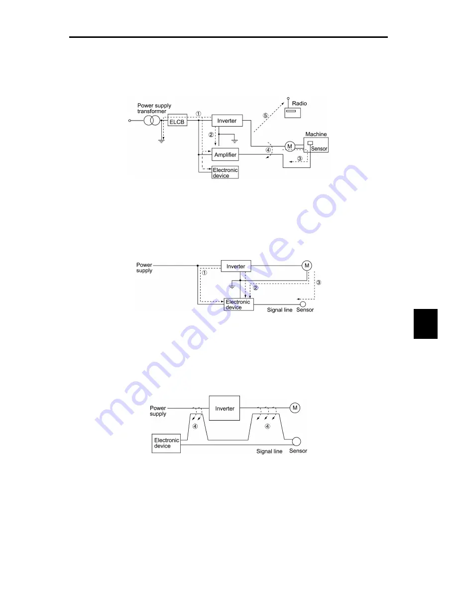
[ 2 ] Types of noise
Noise generated in an inverter is propagated through the main circuit wiring to the power supply and
the motor so as to affect a wide range of applications from the power supply transformer to the
motor. The various propagation routes are shown in Figure A.2. According to those routes, noises
are roughly classified into three types--conduction noise, induction noise, and radiation noise.
Figure A.2 Noise Propagation Routes
(1) Conduction noise
Noise generated in an inverter may propagate through the conductor and power supply so as to affect
peripheral devices of the inverter (Figure A.3). This noise is called "conduction noise." Some
conduction noises will propagate through the main circuit
. If the ground wires are connected to a
common ground, conduction noise will propagate through route
. As shown in route
, some
conduction noises will propagate through signal lines or shielded wires.
Figure A.3 Conduction Noise
(2) Induction noise
When wires or signal lines of peripheral devices are brought close to the wires on the input and
output sides of the inverter through which noise current is flowing, noise will be induced into those
wires and signal lines of the devices by electromagnetic induction (Figure A.4) or electrostatic
induction (Figure A.5). This is called "induction noise"
.
Figure A.4 Electromagnetic Noise
Содержание frenic mini series
Страница 1: ...USER S MANUAL Fuji Electric Co Ltd MEH446...
Страница 2: ...Compact Inverter User s Manual...
Страница 60: ...4 2 4 2 Drive Frequency Command Generator Figure 4 1 Block Diagram for Drive Frequency Command Generator...
Страница 62: ...4 4 4 3 Drive Command Generator Figure 4 2 Drive Command Generator...
Страница 66: ...4 8 Figure 4 3 d Terminal Command Decoder ORing with Link Commands Ignoring Link Commands...
Страница 68: ...4 10 4 5 Digital Output Selector Figure 4 4 Digital Output Signal Selector...
Страница 70: ...4 12 4 6 Analog Output FMA Selector Figure 4 5 Analog Output FMA Selector...
Страница 72: ...4 14 4 7 Drive Command Controller Figure 4 6 Drive Command Controller and Related Part of the Inverter...
Страница 74: ...4 16 4 8 PID Frequency Command Generator Figure 4 7 PID Frequency Command Generator...
Страница 81: ...Part 3 Peripheral Equipment and Options Chapter 6 SELECTING PERIPHERAL EQUIPMENT...
Страница 109: ...Part 4 Selecting Optimal Inverter Model Chapter 7 SELECTING OPTIMAL MOTOR AND INVERTER CAPACITIES...
Страница 124: ...Part 5 Specifications Chapter 8 SPECIFICATIONS Chapter 9 FUNCTION CODES...
Страница 134: ...8 3 Common Specifications 8 9 Chap 8 SPECIFICATIONS 8 3 Common Specifications...
Страница 135: ...8 10...
Страница 257: ...App H Replacement Information A 33 App FVR C11S vs FRENIC Mini...
Страница 261: ...Glossary This glossary explains the technical terms that are frequently used in this manual...


