42
• Setting the DIP Switches
ZMA-330, Ver.6
PosiDRIVE Security Gate
12.
When the gate arm provides the appropriate amount of resistance, reconnect power
and close up the gate as follows:
a.
Ensure all technicians are clear of the drive mechanism and the gate arm path.
b.
Replace the enclosure cap.
c.
Connect the battery backup.
d.
Turn on the circuit breaker switch.
e.
Close the enclosure door.
Setting the DIP Switches
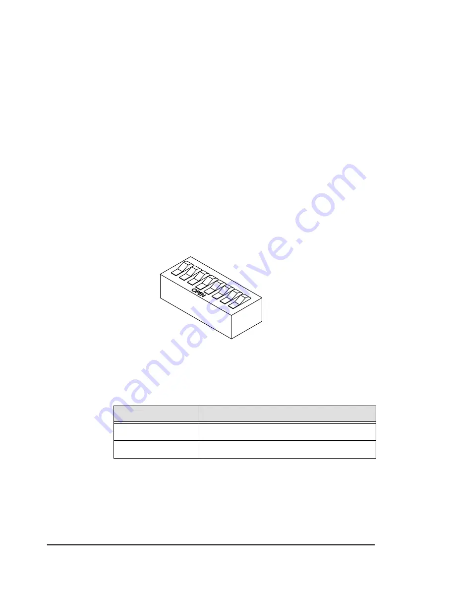
Set the SW2 DIP switches on the PosiDRIVE Controller (Figure 1.9, on page 14) for the
gate to function as intended. Figure 2.19 shows the DIP switches in the “open” position.
Descriptions of the DIP switch functions follow the illustration.
Note:
DIP switch 2 is unused.
Figure 2.19
DIP switches in the Open Position
DIP Switch 1: Vend Counts
The following table lists the DIP switch positions to enable or disable vend
counts.
Table 2-3 —
Vend Count Enabled/Disabled DIP Switch Settings
Values
DIP Switch Positions
Vend counts enabled
DIP switch 1 closed
Vend counts disabled
DIP switch 1 open
Содержание PosiDRIVE
Страница 1: ...PosiDRIVE Security Gate Installation Operation and Maintenance Manual ...
Страница 2: ......
Страница 26: ...18 Removing the Enclosure Cap ZMA 330 Ver 6 PosiDRIVE Security Gate ...
Страница 64: ...56 Aligning the Drive Mechanism ZMA 330 Ver 6 PosiDRIVE Security Gate ...
Страница 68: ...60 Accessing the Distributor Resource Center ZMA 330 Ver 6 PosiDRIVE Security Gate ...
Страница 90: ...82 Requesting a Repair ZMA 330 Ver 6 PosiDRIVE Security Gate ...
Страница 94: ...86 Index ZMA 330 Ver 6 PosiDRIVE Security Gate ...
Страница 95: ......


