


5-29
In general, specify data of function code F20 at a value close to the rated slip
frequency of motor. If you set it at an extremely high value, control may become
unstable and an overvoltage alarm may result in some cases.
The DC brake function of the inverter does not provide any holding mechanism.
Injuries could occur.
F23
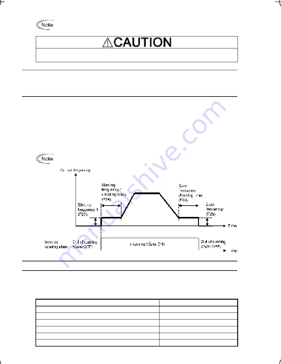
Starting Frequency 1
Starting Frequency 1 (Holding time)
Stop Frequency
Stop Frequency (Holding time)
F24
F25
F39
At the startup of an inverter, the initial output frequency is equal to the starting frequency 1
specified by F23. The inverter stops its output when the output frequency reaches the stop
startup.
shment of a magnetic flux in the motor. F39 specifies the
frequency
Set the st
specified by F25.
arting frequency to a level at which the motor can generate enough torque for
Generally, set the motor's rated slip frequency as the starting frequency.
In addition, F24 specifies the holding time for the starting frequency 1 in order to compensate
for the delay time for the establi
holding time for the stop frequency in order to stabilize the motor speed at the stop of the
motor.
If the starting frequency is lower than the stop frequency, the inverter will not output
any power as long as the reference frequency does not exceed the stop frequency.
F26, F27
Motor Sound (Carrier frequency and tone)
Motor sound (C
F26 co
s the
b
electromagnetic
ec
main output (sec
Carrier frequency
arrier frequency) (F26)
ntrol
carrier frequency so as to reduce an audi
noise from the inverter itself, and to d
ondary) wirings.
le noise generated by the motor or
rease a leakage current from the
0.75 to 15 kHz
Motor sound noise emission
High
↔
Low
Motor te
mponents)
High
↔
Low
mperature (due to harmonics co
Ripples in output current waveform
Large
↔
Small
Leakag
Low
↔
High
e current
Electromagnetic noise emission
Low
↔
High
Inverter loss
Low
↔
High


