


5-33
In the slip compensation and dynamic torque vector control, the inverter uses the
motor parameters to control its speed. Therefore, the following conditions should be
satisfied; if not, the inverter may not get the proper performance from the mo
.
• A single motor should be controlled. (It is difficult to
tor
apply this control to a group
motor driving system.)
03 and P06 to P12 are properly configured or they are
ranks lower than that of the
f the motor lowers, causing
ccurately control the motor.
iring
or input terminals should not
ceed 50
t suppress the earth leakage
urrent sinc
pacitance against the earth increases,
sing it di
eed.
F43, F44
• Motor parameters P02, P
fully auto-tuned.
• The rating of the motor to be controlled should be two
inverter. If not, the output current detection sensibility o
it difficult to a
• The w
ex
between the inverter output and mot
m in length. A long wiring run could no
c
e the cable's electrostatic ca
cau
fficult to accurately control the motor sp
Current Limiter (Mode selection, Level)
hen the output current of the inverter exceeds the level specified by the current limiter (F44),
tomatically manages its output frequency to prevent a stall and limit the output
of acceleration and constant speed operation. Choose
3 = 1 if you need to run the inverter at full capability during acceleration and to limit the
onstant speed operation.
W
the inverter au
current. (Refer to the description of function code H12.)
If F43 = 1, the current limiter is enabled only during constant speed operation. If F43 = 2, the
current limiter is enabled during both
F4
output current during c
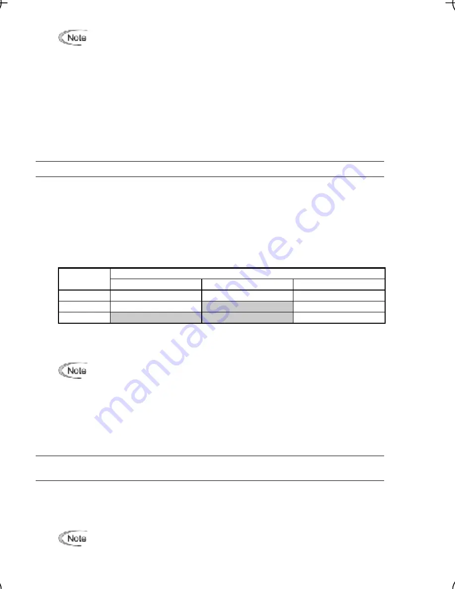
Mode selection (F43)
F43 selects the motor running state in which the current limiter will be active.
Running states that enable the current limiter
Data for
F43
During acceleration
During constant speed
During deceleration
0 Disable
Disable
Disable
1 Disable
Enable
Disable
2
Enable
Enable
Disable
s the operation level at which the output current limiter becomes activated, in ratio
to
ating.
Level (F44)
F44 specifie
the inverter r
• Since
t limit
43
rm
i
the curren
operation with F
and F44 is perfo
ed by software, t
may
ay in c
d a qu
spec
opera
ardware (H1
the same t
• If an
cu
ter operatio
s se
cause a del
ontrol. If you nee
ick response,
ify a current limit
tion by h
2 = 1) at
ime.
excessive load is applied when the
rrent limi
n level i
t
extrem
the inverter
ly lower its
equency. Th
ause
an ov
e trip or d
s turnover
motor rot
e to
under
• The torque limiter and current limiter are very similar function each other. If both
ntly, they may conflict each other and cause a hunting in
F50
ely low,
will rapid
output fr
is may c
ervoltag
angerou
of the
ation du
shooting.
are activated concurre
the system. Avoid concurrent activation of these limiters.
, F51
Electronic Thermal Overload Protection for Braking Resistor
(Discharging capability and Allowable average loss)
he specifications of the braking resistor, as listed on the
These function codes specify the electronic thermal overload protection feature for the braking
resistor.
Set F50 and F51 data to the discharging capability and allowable average loss, respectively.
Those values differ depending on t
following pages.
Depending on the thermal marginal characteristics of the braking resistor, the
electronic thermal overload protection feature may act so that the inverter issues the
overheat protection alarm
dbh
even if the actual temperature rise is not enough. If it
happe
resisto
ns, review the relationship between the performance index of the braking
r and settings of related function codes.


