


5-31
F
F
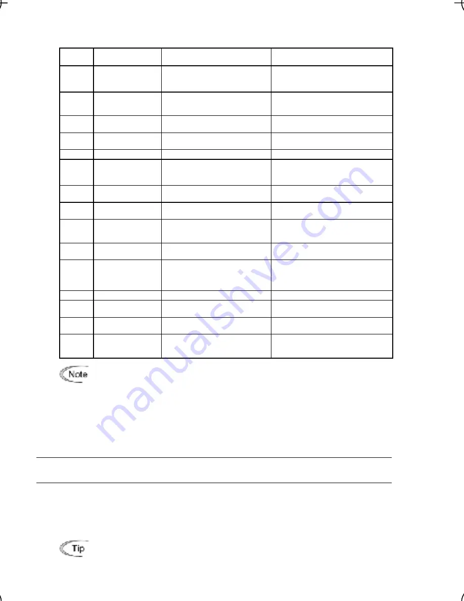
unction (F31)
specifies what is output to analog output terminal [FM].
ata for
F31
[FM] output
Function
(Monitor the following)
Meter scale
(Full scale at 100%)
31
D
0
(before slip
compensation)
(Equivalent to the motor
synchronous speed)
Maximum frequency (F03/A01)
Output frequency
Output frequency of the inverter
1
Output frequency
(after slip
compensation)
Output frequency of the inverter
Maximum frequency (F03/A01)
2
Output current
Output current (RMS) of the
inverter
Twice the inverter rated current
Output voltage (RMS) of the
inverter
250 V for 200 V class series,
500 V for 400 V class series
3
Output voltage
4
Output torque
Motor shaft torque
Twice the rated motor torque
5
Load factor
Load factor
(Equivalent to the indication of
the load meter)
Twice the rated motor load
Input power
Input power of the inverter
Twice the rated output of the
inverter
6
7
100% of the feedback amount
PID feedback
amount (PV)
Feedback amount under PID
control
8
PG feedback value
control through the PG
interface
(100% of the feedbac
Feedback value of closed loop
Maximum speed
k value)
9
age of the
500 V for 200 V class series,
DC link bus
DC link bus volt
voltage
inverter
1000 V for 400 V class series
10
Universal AO
Command via communications
link (Refer to the RS-485
Communication User's Manual
(MEH448b).)
20000 as 100%
13
Motor output
Motor output (kW)
Twice the rated motor output
14
Calibration
Full scale output of the meter
calibration
This always outputs the full-scale
(100%).
15
PID command
(SV)
Command value under PID
control
100% of the feedback amount
utput (MV)
O
e PID
co
ID control
utput level of th
ntroller under P
(Frequency command)
Maximum frequency (F03/A01)
16
PID o
If F31
er control), and J
or 3 (Ratio
compen
alent to the ratio
st the primar
= 16 (PID output), J01 = 3 (Danc
sation enabled), the PID output is equiv
62 = 2
again
y
reference frequency and may vary within
±
300% of the frequency. The monitor
d absolute value. To indicate the value up to
"33" (%).
F33 specifies the number of pulses at which the output of the monitored item selected reaches
100%, in accordance with the specifications of the counter to be connected.
F40, F41
E16, E17
Torque Limiter 1 (Limiting levels for driving and braking)
Torque Limiter 2 (Limiting levels for driving and braking)
displays the PID output in a converte
the full-scale of 300%, set F30 data to
Pulse rate (F33) dedicated to
FMP
If the inverter’s output torque exceeds the specified levels of the driving torque limiter
(F40/E16) and the braking torque limiter (F41/E17), the inverter controls the output frequency
and limits the output torque for preventing a stall.
Specify the limiting levels at which the torque limiter becomes activated, as the percentage of
the motor rated torque.
To switch the inverter’s output torque limiter between torque limiter 1 (F40/F41) and
torque limiter 2 (E16/E17), use the terminal command
TL2/TL1
assigned to a digital
input terminal. (Refer to the descriptions of E01 to E05.)


