


QFE
page 3-13
Applications
FD841405_F
Obviously, the larger the difference, the faster the acceleration and the quicker full speed is
reached - and, coincidentally, the greater the stresses experienced by the supply and drive
systems during the acceleration process. An “ideal” start would accelerate the load with just
sufficient force to reach full speed smoothly in a reasonable time, and with minimum stress
to the supply and drive mechanisms.
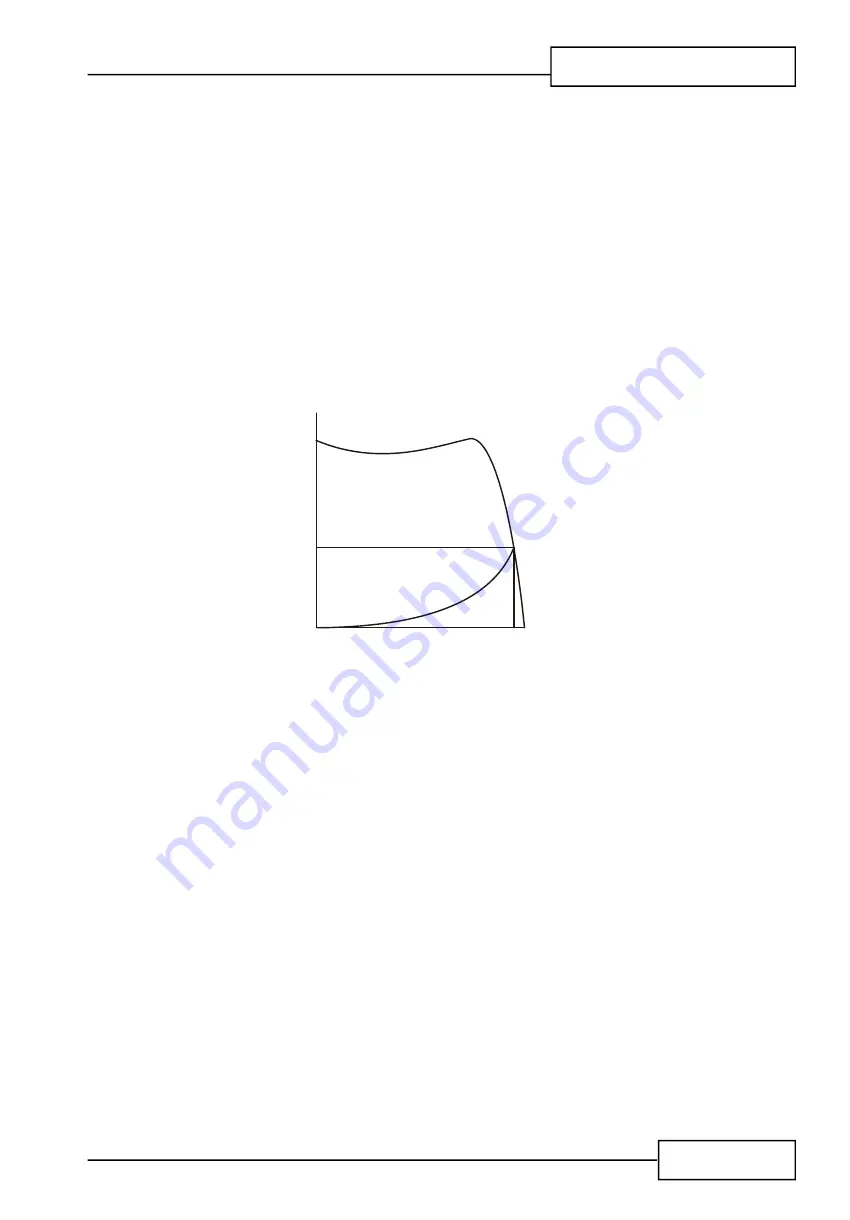
Broadly speaking, the motor speed/torque characteristic is controlled by the rotor resistance
- a motor with high rotor resistance can generate it’s peak torque (pull-out torque) at standstill
giving the high break-away torque characteristic, which reduces steadily as the speed
increases and becoming zero at synchronous speed. At the other end of the scale, a motor
with a very low rotor resistance will produce a low starting torque but will generate its peak
torque closer to the synchronous speed. Consequently this type of motor runs at full power
with higher operating efficiency and low slip speed. It is possible to combine the twin
requirements of high starting torque and efficient full-speed operation within a single motor
by techniques such as double-cage or deep bar design, and this, usually, is the motor
characteristic chosen for lifting and hoisting applications:
Locked Rotor Torque
( LRT, M )
A
Pull Out Torque
( M )
K
TORQUE
Pull-up Torque
Full Load Torque ( FLT, M )
N
Synchronous speed
0
S
SPEED
Figure 3.3.2.4 Torque/Speed Curve - High Starting Torque
However, most induction motors are designed to have a “standard” characteristic that provides
a compromise between starting torque and operating efficiency. To summarise, an induction
motor will only start and accelerate when it produces more torque than the connected load
absorbs. This is true for all speeds - including standstill and full speed.
3.3.3
Starting Induction Motors
Starting a de-magnetised induction motor from standstill is a demanding and complex process.
At the instant of switching all the energy necessary to magnetise the motor, to provide the
acceleration force, and to supply the kinetic energy of the rotor and load, must be present
together with the energy to overcome the mechanical and electrical losses. To do so at full
supply voltage places considerable stresses on the supply, the motor windings, and the iron
cores of the stator and rotor. Excessive acceleration of a rotor when the mechanical load is
small can produce torque oscillations in the shaft causing severe wear to transmissions,
gears and drives. Excessive acceleration when the load inertia is high such as in centrifugal
fans, causes belts to slip in the pulleys, producing rapid wear and early failure.
Содержание QFE Series
Страница 17: ...QFE Soft Start Motor Controller Technical Data for the QFE and QFEplus Mechanical Installation FD841205_F...
Страница 18: ...Mechanical Installation QFE page 1 2 FD841205_F...
Страница 26: ...Mechanical Installation QFE page 1 10 FD841205_F...
Страница 27: ...QFE Soft Start Motor Controller Technical Data for the QFE and QFEplus Electrical Installation FD8413 issue03_F...
Страница 43: ...QFE page 2 19 Electrical Installation FD8413 issue03_F...
Страница 50: ...Electrical Installation QFE page 2 26 FD8413 issue03_F...
Страница 51: ...QFE Soft Start Motor Controller Technical Data for the QFE and QFEplus Applications...
Страница 73: ...QFE page 3 25 Applications FD841405_F...
Страница 112: ...QFE Soft Start Motor Controller Technical Data for the QFE and QFEplus Programming Guide FD8420 issue02_F...
Страница 158: ...page 5 47 Programming QFE FD8420 issue02_F This page is left intentionally blank...
Страница 181: ...Modbus page 6 4 5MC FD510007...


