


Epson Research and Development
Page 25
Vancouver Design Center
Programming Notes and Examples
SED1352
Issue Date: 98/10/08
X16-BG-007-04
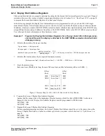
4.2.2 Display Start Address Registers
This section illustrates how to properly calculate the values for the Screen Start Address Registers for a given LCD panel
resolution. However, this section is limited to single panel displays; refer to Section 5.4.4, “Dual Panel LCD” on page 38
to program the Screen Start Address Registers for a dual panel display.
In the following example, the Display Start Address Registers are programmed for a 16 gray shade 320 x 240 single
monochrome display. The technique shown, however, can also be used to calculate the memory map of other resolutions.
In addition, reference is made to the SDU1352B0x evaluation board; other hardware implementations of the SED1352 may
assign different display and port addresses from those of the SDU1352B0x. Refer to the SDU1352B0x Evaluation Board
User’s Manual for more information on these hardware issues.
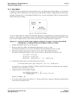
Example 7:
Program the Display Start Address Registers for a 16 gray shade 320 x 240 single mono-
chrome LCD panel; the display is attached to the SDU1352B0x evaluation board with 64k
of display memory.
1.
Calculate the number of bytes per scan line.
2.
Calculate the total number of bytes required for display memory.
3.
Create the memory map.
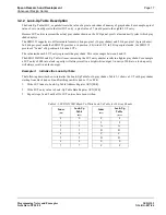
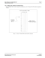
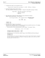
Each scan line is 00A0h bytes long, there are 240 scan lines, and the last memory address is 9600h - 1.
Figure 5: Memory Map for 320 x 240 LCD Panel with 16 Gray Shades
4.
Program the Screen 1 Display Start Address Registers.
Assume that the image starts at the beginning of display memory, which for 64k is D000:0000h. As shown in
Example 6, the Screen 1 Display Start Address Registers must be programmed to 8000h words.
AUX[06h] = 00h
AUX[07h] = 80h
5.
Program the Screen 2 Display Start Address Registers.
Under normal programming conditions, the Screen 2 Display Start Address should be set to the same value as the
Screen 1 Display Start Address. In the event that a split screen is required, refer to Section 5.4, “Split Screen” on
page 34.
AUX[08h] = 00h
AUX[09h] = 80h
Offset
(hex)
Offset
(hex)
0000
Scan Line 0
009F
00A0
Scan Line 1
013F
94C0
Scan Line 238
955F
9560
Scan Line 239
95FF
16 gray shades => 4 bits per pixel
4 bits per pixel => 2 pixels per byte
number of bytes per scan line
pixels per scan line
pixels per byte
----------------------------------------------
320
2
---------
160 bytes per scan line
00A0h bytes per scan line
=
=
=
=
bytes per scan line
(
)
number of scan lines
(
)
×
160
240
×
38400 bytes
9600h bytes
=
=
=