


Page 24
Epson Research and Development
Vancouver Design Center
SED1352
Programming Notes and Examples
X16-BG-007-04
Issue Date: 98/10/08
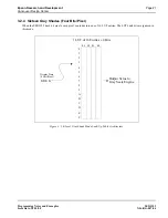
4.2 Description
When displaying an image, the SED1352 must read pixel data from display memory. This memory is organized to match
the display resolution of the given LCD panel. To organize display memory, the following registers must be programmed:
1.
Screen 1 Display Start Address Registers.
2.
Screen 2 Display Start Address Registers.
3.
Address Pitch Adjustment Register.
For the first example, the Address Pitch Adjustment Register is programmed to zero. This means that no virtual display is
available; for information on virtual displays see Section 5.1, “Virtual Displays” on page 28.
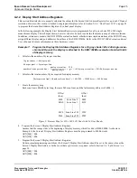
4.2.1 SDU1352B0x Evaluation Board Display Memory
There are several issues to consider when programming the Screen Display Start Address Registers for the SDU1352B0x
evaluation board:
•
When the SDU1352B0x is set for 64k of display memory, display memory exists from address D000:0000h to
address D000:FFFFh. When the SDU1352B0x is set for 128k of display memory, display memory exists from
address C000:0000h to address D000:FFFFh.
•
For the SDU1352B0x, the Screen Display Start Address Registers are always in reference to the display memory
address C000:0000h. Writing 0 to a Display Start Address Register will always refer to C000:0000h, even if display
memory only exists from D000:0000h to D000:FFFFh. Consequently if only 64k of display memory is present, 64k
must be added to the display address in order to point to D000:0000h. This is a limitation of the evaluation board
only.
•
Although the SED1352 can set the Memory Interface to 8 or 16 bits, the SDU1352B0x evaluation board should be set
up for 16 bits. As a result, the Display Start Address Registers are word pointers, not byte pointers. To illustrate how
to use a word pointer, refer to Example 6. In general, any system which uses more than 64k of display memory must
always have the Memory Interface set to 16 bits.
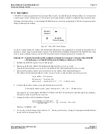
Example 6:
For the SDU1352B0x, calculate the required start address register value which refers to
location D000:0000h.
Since a value of 0 refers to location C000:0000h, the start address register must be programmed with an offset address of
1000:0000h = 10000h bytes, or 8000h words.
START ADDRESS[LSB] = 00h
START ADDRESS[MSB] = 80h