


Epson Research and Development
Page 41
Vancouver Design Center
Programming Notes and Examples
SED1352
Issue Date: 98/10/08
X16-BG-007-04
6.
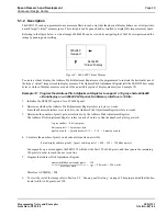
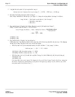
Determine the display memory location for image 2.
Place image 2 immediately after image 1 (see Figure 14). Assign the starting address for image 2 as follows:
7.
Program the Screen 2 Display Start Address Register to point to the beginning of image 2.
Image 2 is placed right after image 1, as shown below:
AUX[08h] = 00h
AUX[09h] = 4Bh
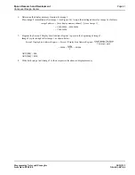
8.
Write both image 1 and image 2 to their respective locations in display memory.
image 2 address
base display memory address
(
)
size of image 1
(
)
+
=
C000:0000h
0000:9600h
+
=
C000:9600h
=
Screen 2 Display Start Address Register
Screen 1 Display Start Address Register
size of image 1 in bytes
2 bytes per word
--------------------------------------------------------
+
=
0000h
9600h
2
---------------
+
4B00h
=
=