


Page 12
Epson Research and Development
Vancouver Design Center
SED1352
Hardware Functional Specification
X16-SP-001-16
Issue Date: 99/07/28
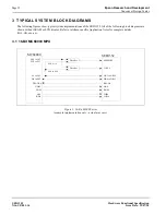
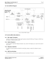
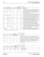
3 TYPICAL SYSTEM BLOCK DIAGRAMS
The following figures show typical system implementations of the SED1352. All of the following block diagrams are
shown without SRAM or LCD display. Refer to interface specific Application Notes for complete details
(X16-AN-xxx-xx).
3.1 16-Bit MC68000 MPU
Figure 1: 16-Bit 68000 Series
(example implementation only - actual may vary)
SED1352
MEMCS#
IOCS#
MC68000
DTACK#
D0 to D15
A1 to A19
AB1 to AB19
DB0 to DB15
IOW#
IOR#
Decoder
AS#
R/W#
BHE#
UDS#
READY
A20 to A23
AB0
LDS#
Decoder
A16. A14
A10 to A19
FC0 to FC1