S1C63656 TECHNICAL MANUAL
EPSON
161
APPENDIX PERIPHERAL CIRCUIT BOARDS FOR S1C63656
A.2 Connecting to the Target System
This section explains how to connect the S5U1C63000P1 to the target system.
First insert the S5U1C63000P1 board into the second upper slot of the ICE and the S5U1C63658P2 board
into the top slot.
Download the circuit data to the S5U1C63000P1 board before installing the S5U1C63658P2 board if the
S5U1C63000P1 board does not include the correct circuit data. See Section A.3 for downloading circuit
data.
S5U1C63658P2
S5U1C63000P1
Fig. A.2.1 Installing the peripheral circuit boards to the ICE
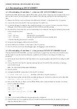
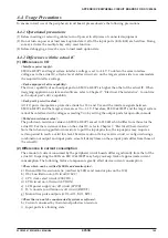
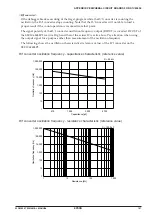
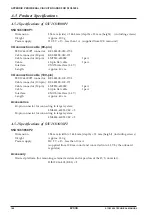
•
Installing the S5U1C63000P1/63658P2 board
Set the jig included with the ICE into position as
shown in Figure A.2.2. Using this jig as a lever,
push it toward the inside of the board evenly on
the left and right sides. After confirming that the
board has been firmly fitted into the internal slot
of the ICE, remove the jig.
Fig. A.2.2
Installing the board
•
Dismounting the S5U1C63000P1/63658P2 board
Set the jig included with the ICE into position as
shown in Figure A.2.3. Using this jig as a lever,
push it toward the outside of the board evenly
on the left and right sides. After confirming that
the board has been dismounted from the
backboard connector, pull the board out of the
ICE.
Fig. A.2.3
Dismounting the board
Board
Board
Содержание S1C63656
Страница 1: ...Technical Manual CMOS 4 BIT SINGLE CHIP MICROCOMPUTER S1C63656 Technical Hardware S1C63656 ...
Страница 4: ......
Страница 6: ......


