S1C63656 TECHNICAL MANUAL
EPSON
29
CHAPTER 4: PERIPHERAL CIRCUITS AND OPERATION (Oscillation Circuit)
4.3.3 OSC3 oscillation circuit
The S1C63656 has built-in the OSC3 oscillation circuit that generates the CPU's sub-clock (Max. 4 MHz)
for high speed operation and the source clock for peripheral circuits needing a high speed clock (pro-
grammable timer, FOUT output). The mask option enables selection of the oscillator type from CR
(external R type), CR (built-in R type) and ceramic oscillation circuit. When CR oscillation (external R
type) is selected, only a resistance is required as an external element. When ceramic oscillation is selected,
a ceramic oscillator and two capacitors (gate and drain capacitance) are required. When CR oscillation
(built-in R type) is selected, no external element is required. If the application needs low-voltage and low-
power operations precedence to performance, the OSC3 oscillation circuit and the high-speed operation
voltage regulator can be disabled by mask option.
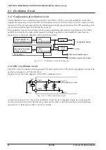
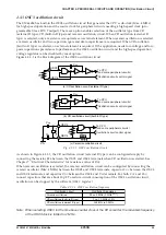
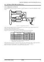
Figure 4.3.3.1 is the block diagram of the OSC3 oscillation circuit.
To CPU
(and some peripheral circuits)
Oscillation circuit control signal
(b) CR oscillation circuit (built-in R type)
(c) Ceramic oscillation circuit
C
CR
R
CR
V
SS
C
GC
C
DC
Ceramic
OSC4
OSC3
R
R
DC
To CPU
(and some peripheral circuits)
Oscillation circuit control signal
FC
To CPU
(and some peripheral circuits)
Oscillation circuit control signal
(a) CR oscillation circuit (external R type)
C
CR
OSC3
OSC4
R
CR
Fig. 4.3.3.1 OSC3 oscillation circuit
As shown in Figure 4.3.3.1, the CR oscillation circuit (external R type) can be configured simply by
connecting the resistor R
CR
between the OSC3 and OSC4 terminals when CR oscillation is selected. See
Chapter 7, "Electrical Characteristics" for resistance value of R
CR
.
When ceramic oscillation is selected, the ceramic oscillation circuit can be configured by connecting the
ceramic oscillator (Max. 4 MHz) between the OSC3 and OSC4 terminals, capacitor C
GC
between the OSC3
and OSC4 terminals, and capacitor C
DC
between the OSC4 and V
SS
terminals. For both C
GC
and C
DC
,
connect capacitors that are about 30 pF. To reduce current consumption of the OSC3 oscillation circuit,
oscillation can be stopped by the software (OSCC register).
Table 4.3.3.1 OSC3 oscillation frequency
Oscillation circuit
Ceramic oscillation
CR oscillation (built-in R type)
CR oscillation (external R type)
Oscillation frequency
Max. 4 MHz (2 MHz
Note
)
Typ. 1.1 MHz
±
30%
200 kHz to 2 MHz
Note: When selecting OSC3 for the time base counter clock of the R/f converter, the maximum frequency
of the OSC3 clock is limited to 2 MHz.
Содержание S1C63656
Страница 1: ...Technical Manual CMOS 4 BIT SINGLE CHIP MICROCOMPUTER S1C63656 Technical Hardware S1C63656 ...
Страница 4: ......
Страница 6: ......

