92
EPSON
S1C63656 TECHNICAL MANUAL
CHAPTER 4: PERIPHERAL CIRCUITS AND OPERATION (Serial Interface)
4.11.5 I/O memory of serial interface
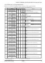
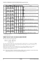
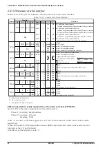
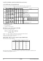
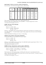
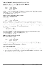
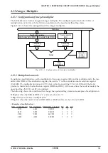
Table 4.11.5.1 shows the I/O addresses and the control bits for the serial interface.
Table 4.11.5.1 Control bits of serial interface
Address
Comment
D3
D2
Register
D1
D0
Name
Init
∗
1
1
0
FF45H
PUL13
PUL12
PUL11
PUL10
R/W
PUL13
PUL12
PUL11
PUL10
1
1
1
1
On
On
On
On
Off
Off
Off
Off
P13 pull-down control register
functions as a general-purpose register when SIF (slave) is selected
P12 pull-down control register (ESIF=0)
functions as a general-purpose register when SIF (master) is selected
SCLK (I) pull-down control register when SIF (slave) is selected
P11 pull-down control register (ESIF=0)
functions as a general-purpose register when SIF is selected
P10 pull-down control register (ESIF=0)
SIN pull-down control register when SIF is selected
0
Slave
2
OSC1/2
1
PT
3
OSC1
R/W
FF72H
SD3
SD2
SD1
SD0
SD3
SD2
SD1
SD0
–
∗
2
–
∗
2
–
∗
2
–
∗
2
High
High
High
High
Low
Low
Low
Low
MSB
Serial I/F transmit/receive data (low-order 4 bits)
LSB
R/W
FF73H
SD7
SD6
SD5
SD4
SD7
SD6
SD5
SD4
–
∗
2
–
∗
2
–
∗
2
–
∗
2
High
High
High
High
Low
Low
Low
Low
MSB
Serial I/F transmit/receive data (high-order 4 bits)
LSB
[SCS1, 0]
Clock
[SCS1, 0]
Clock
FF71H
SDP
SCPS
SCS1
SCS0
R/W
SDP
SCPS
SCS1
SCS0
0
0
0
0
MSB first LSB first
Serial I/F data input/output permutation
Serial I/F clock phase selection
–Negative polarity (mask option)
–Positive polarity (mask option)
Serial I/F
clock mode selection
FF70H
0
ESOUT SCTRG
ESIF
R
R/W
0
∗
3
ESOUT
SCTRG
ESIF
–
∗
2
0
0
0
Enable
Trigger
Run
SIF
Disable
Invalid
Stop
I/O
Unused
SOUT enable
Serial I/F clock trigger (writing)
Serial I/F clock status (reading)
Serial I/F enable (P1 port function selection)
FFF2H
0
0
0
ISIF
R
R/W
0
∗
3
0
∗
3
0
∗
3
ISIF
–
∗
2
–
∗
2
–
∗
2
0
(R)
Yes
(W)
Reset
(R)
No
(W)
Invalid
Unused
Unused
Unused
Interrupt factor flag (Serial I/F)
FFE2H
0
0
0
EISIF
R
R/W
0
∗
3
0
∗
3
0
∗
3
EISIF
–
∗
2
–
∗
2
–
∗
2
0
Enable
Mask
Unused
Unused
Unused
Interrupt mask register (Serial I/F)
*1 Initial value at initial reset
*2 Not set in the circuit
*3 Constantly "0" when being read
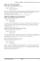
ESIF: Serial interface enable register (P1 port function selection) (FF70H•D0)
Sets P10–P13 to the input/output port for the serial interface.
When "1" is written: Serial interface
When "0" is written: I/O port
Reading: Valid
When "1" is written to the ESIF register, P10, P11, P12 and P13 function as SIN, SOUT, SCLK, SRDY,
respectively.
In the slave mode, the P13 terminal functions as SRDY output terminal, while in the master mode, it
functions as the I/O port terminal.
At initial reset, this register is set to "0".
Содержание S1C63656
Страница 1: ...Technical Manual CMOS 4 BIT SINGLE CHIP MICROCOMPUTER S1C63656 Technical Hardware S1C63656 ...
Страница 4: ......
Страница 6: ......


