S1C63656 TECHNICAL MANUAL
EPSON
63
CHAPTER 4: PERIPHERAL CIRCUITS AND OPERATION (Stopwatch Timer)
4.9.4 Stopwatch timer RUN/STOP and reset
RUN/STOP control and reset of the stopwatch timer can be done by the software.
Stopwatch timer RUN/STOP
The stopwatch timer enters the RUN status when "1" is written to SWRUN, and the STOP status when
"0" is written. In the STOP status, the timer data is maintained until the next RUN status or resets
timer. Also, when the STOP status changes to the RUN status, the data that was maintained can be
used for resuming the count. The RUN/STOP operation of the stopwatch timer by writing to the
SWRUN register is performed in synchronization with the falling edge of the 1,024 Hz same as the
prescaler input clock. The SWRUN register can be read, and in this case it indicates the operating
status of the stopwatch timer.
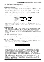
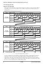
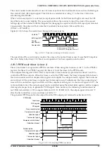
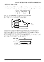
Figure 4.9.4.1 shows the operating timing when controlling the SWRUN register.
f
OSC1
/32 (1,024 Hz)
SWRUN writing
SWRUN register
Count clock
Fig. 4.9.4.1 Operating timing when controlling SWRUN
When the direct input function (explained in next section) is set, RUN/STOP control is done by an
external key input. In this case, SWRUN becomes read only register that indicates the operating status
of the stopwatch timer.
Stopwatch timer reset
The stopwatch timer is reset when "1" is written to SWRST. With this, the counter value is cleared to
"000". Since this resetting does not affect the capture buffer, data that has been held in the capture
buffer is not cleared and is maintained as is. When the stopwatch timer is reset in the RUN status,
counting restarts from count "000". Also, in the STOP status the reset data "000" is maintained until the
next RUN.
4.9.5 Direct input function and key mask
The stopwatch timer has a direct input function that can control the RUN/STOP and LAP operation of
the stopwatch timer by external key input. This function is set by writing "1" to the EDIR register. When
EDIR is set to "0", only the software control is possible as explained in the previous section.
Input port configuration
In the direct input function, the input ports K00 and K01 are used as the RUN/STOP and LAP input
ports. The key assignment can be selected using the SWDIR register.
Table 4.9.5.1 RUN/STOP and LAP input ports
SWDIR
0
1
K00
RUN/STOP
LAP
K01
LAP
RUN/STOP
Direct RUN
When the direct input function is selected, RUN/STOP operation of the stopwatch timer can be
controlled by using the key connected to the input port K00/K01 (selected by SWDIR). K00/K01
works as a normal input port, but the input signal is sent to the stopwatch control circuit. The key
input signal from the K00/K01 port works as a toggle switch. When it is input in STOP status, the
stopwatch timer runs, and in RUN status, the stopwatch timer stops. RUN/STOP status of the
stopwatch timer can be checked by reading the SWRUN register. An interrupt is generated by direct
RUN input.
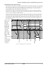
The sampling for key input signal is performed at the falling edge of 1,024 Hz signal same as the
SWRUN control. The chattering judgment is performed at the point where the key turns off, and a
chattering less than 46.8–62.5 msec is removed. Therefore, more time is needed for an interval be-
tween RUN and STOP key inputs.
Содержание S1C63656
Страница 1: ...Technical Manual CMOS 4 BIT SINGLE CHIP MICROCOMPUTER S1C63656 Technical Hardware S1C63656 ...
Страница 4: ......
Страница 6: ......


