S1C63656 TECHNICAL MANUAL
EPSON
113
CHAPTER 4: PERIPHERAL CIRCUITS AND OPERATION (R/f Converter)
Interrupt is generated
Input clock
RFRUNR register
RFIN0/1
Time base counter clock
Time base counter
Measurement counter clock
RFOUT output
Measurement counter
n
*
n+1
n+2
FFFFFH
00000H
*
: Initial setting value (complement) for counting of reference resistance
00000H FFFFFH FFFFEH FFFFDH FFFFCH FFFFBH
x+3
x+2
x+1
x
Time base counter starts counting (count-down)
Starts measurement of reference resistance
Measurement counter starts counting
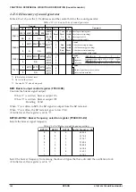
Fig. 4.14.3.1 Reference oscillation timing chart
CR oscillation starts in synchronization with the falling edge of the input clock immediately after
writing "1" to the RFRUNR register. The measurement counter starts counting up at the falling edge of
the first clock after CR oscillation is initiated. The time base counter is enabled at the falling edge of
the first input clock. Then, it counts down by the rising edge of the input clock. The RFRUNR register
is set to "0" at the falling edge of the input clock immediately after the measurement counter stops.
Interrupt conditions are sampled with the OSC1 clock, so an interrupt occurs in synchronization with
the rising edge of the OSC1 clock immediately after the RFRUNR register is set to "0".
An R/f conversion for the sensor starts by writing "1" to the register RFRUNS. When performing this
sensor oscillation after an reference oscillation has completed, it is not necessary to set initial values to
the counters. If converting the sensor resistance independently, the measurement counter must be set
to 00000H and the time base counter must be set to the value measured at the time of a reference
oscillation. When R/f conversion is initiated by the RFRUNS register, oscillation by the sensor begins,
and the measurement counter starts counting up from 00000H by the oscillation clock. The time base
counter also starts counting up by the input clock. If the time base counter becomes 00000H, the
oscillation is terminated. At the same time an interrupt occurs and the RFRUNS register is set to "0",
and the R/f converter circuit stops operation completely.
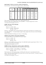
Figure 4.14.3.2 shows a timing chart for the sensor oscillation.
00000H
00001H
00002H
n-1
n
*
x
x+1
x+2
x+3
x+4
x+5
FFFFEH FFFFFH 00000H
Interrupt is generated
Time up
Input clock
RFRUNS register
RFIN0/1
Time base counter clock
Time base counter
Measurement counter clock
RFOUT output
Measurement counter
Starts measurement of sensor
Time base counter starts counting (count-up)
*
: Number of counts during sensor oscillation
Measurement counter starts counting
Fig. 4.14.3.2 Sensor oscillation timing chart
The sensor oscillation starts in synchronization with the falling edge of the input clock immediately
after writing "1" to the RFRUNS register. The measurement counter starts counting up at the falling
edge of the first clock after CR oscillation is initiated.
The time base counter is enabled at the falling edge of the first input clock. Then, it counts up by the
rising edge of the input clock. Depending on the timing, the measurement counter may not count the CR
oscillation clock at the time RFRUNS is set to "0".
Содержание S1C63656
Страница 1: ...Technical Manual CMOS 4 BIT SINGLE CHIP MICROCOMPUTER S1C63656 Technical Hardware S1C63656 ...
Страница 4: ......
Страница 6: ......


