S1C63656 TECHNICAL MANUAL
EPSON
77
CHAPTER 4: PERIPHERAL CIRCUITS AND OPERATION (Programmable Timer)
4.10.8 Control of TOUT output
The programmable timer can generate a TOUT signal from the timer underflow and compare match
signals. The TOUT signal is generated by dividing the underflow signal by 2 in the normal mode. In the
PWM mode, the PWM signal generated by timer 0/1 is output as the TOUT signal. It is possible to select
which timer output is to be used by the TOUT output channel selection register CHSEL0.
Table 4.10.8.1 Selecting a timer for TOUT output
CHSEL0
1
0
TOUT output timer
Timer 1
Timer 0
Select timer 1 when generating the TOUT signal from the 16-bit timer output.
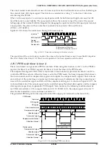
The TOUT signal can be output from the R02 output port terminal.
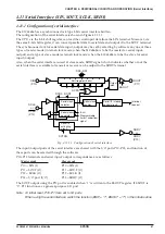
Figure 4.10.8.1 shows the configuration of the output port R02.
Data bus
Register
PTOUT
Register
R02
TOUT
R02
(TOUT)
Register
R02HIZ
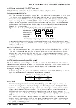
Fig. 4.10.8.1 Configuration of R02
The output of a TOUT signal is controlled by the PTOUT register. When "1" is written to the PTOUT
register, the TOUT signal is output from the R02 output port terminal and when "0" is written, the
terminal goes to a high (V
DD
) level. However, the data register R02 must always be "1" and the high
impedance control register R02HIZ must always be "0" (data output state).
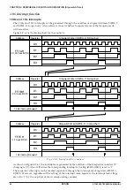
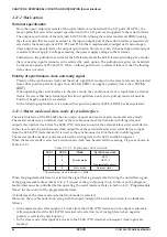
Since the TOUT signal is generated asynchronously from the PTOUT register, a hazard within 1/2 cycle is
generated when the signal is turned on and off by setting the register.
Figure 4.10.8.2 shows the output waveform of the TOUT signal.
R02HIZ register
R02 register
PTOUT register
TOUT output
Fix at "0"
Fix at "1"
"1"
"0"
"0"
Fig. 4.10.8.2 Output waveform of the TOUT signal
Содержание S1C63656
Страница 1: ...Technical Manual CMOS 4 BIT SINGLE CHIP MICROCOMPUTER S1C63656 Technical Hardware S1C63656 ...
Страница 4: ......
Страница 6: ......

